Displacement sensor using multiple position sensitive photodetectors

a technology of photodetectors and displacement sensors, applied in the field of displacement sensors, can solve the problems of limiting the range to resolution ratio, and the device of the '079 patent suffers from an undesired limited range to resolution ratio

Active Publication Date: 2012-10-18
MITUTOYO CORP
View PDF3 Cites 7 Cited by
  • Summary
  • Abstract
  • Description
  • Claims
  • Application Information

AI Technical Summary

Benefits of technology

[0016]In some embodiments, the aperture configuration may be configured to input the source light and output the measurement light to first, second and third detection tracks which are aligned along the measuring axis direction and are spaced apart transverse to the measuring axis direction; the multiple PSD arrangement may further comprise at least a third position sensitive detector comprising a photodetector having a sensitive axis aligned along the third detection track to receive measurement light from the aperture configuration; the second position sensitive detector and the third position sensitive detector may be arranged such that during operation, the second position sensitive detector outputs the

Problems solved by technology

However, the devices of the '722 and '635 patents suffer from remaining unrecognized errors associated with their light sources, which lead to signal nonlinearity and/o

Method used


Image

  • Displacement sensor using multiple position sensitive photodetectors
  • Displacement sensor using multiple position sensitive photodetectors
  • Displacement sensor using multiple position sensitive photodetectors

Examples


first embodiment

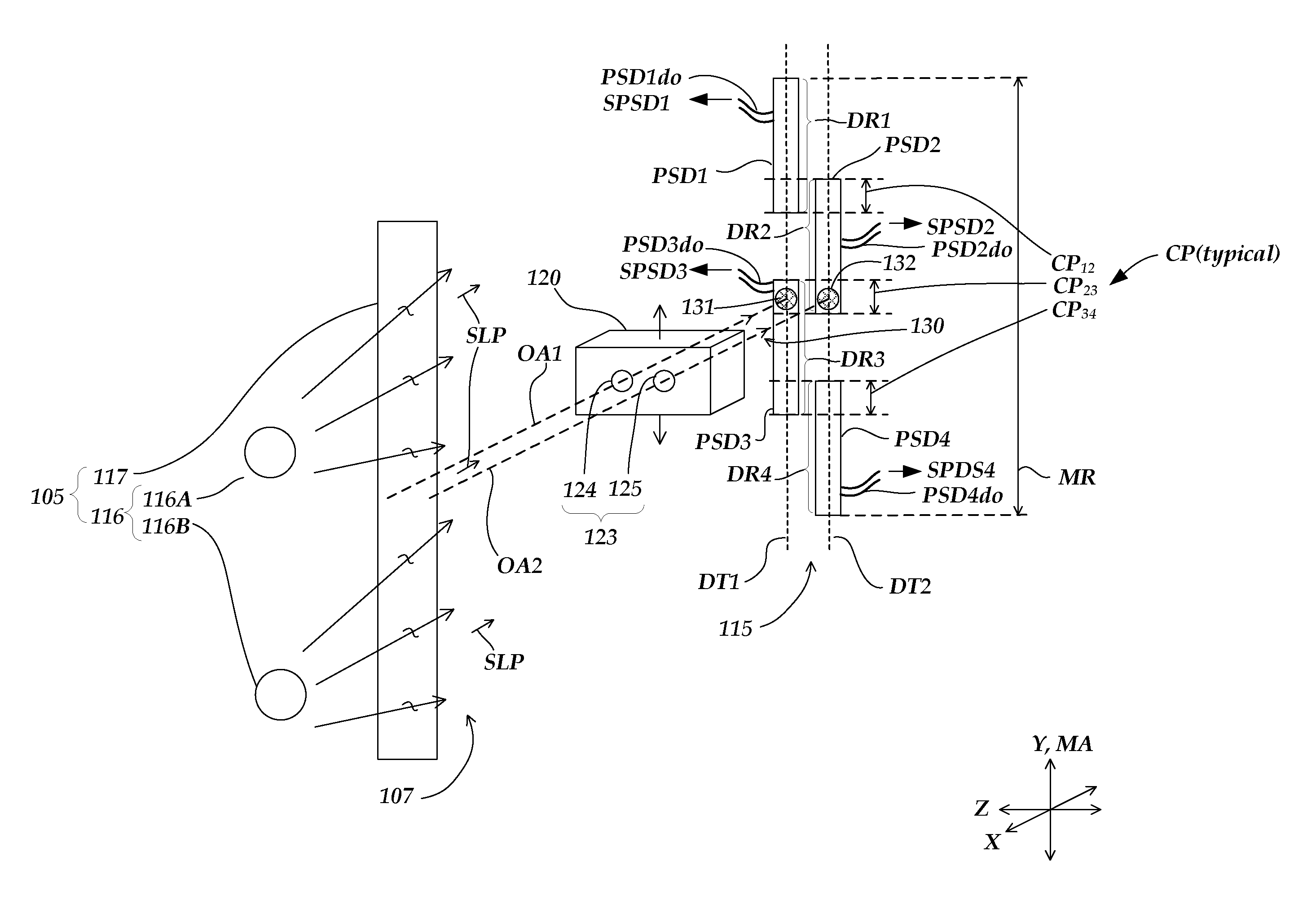
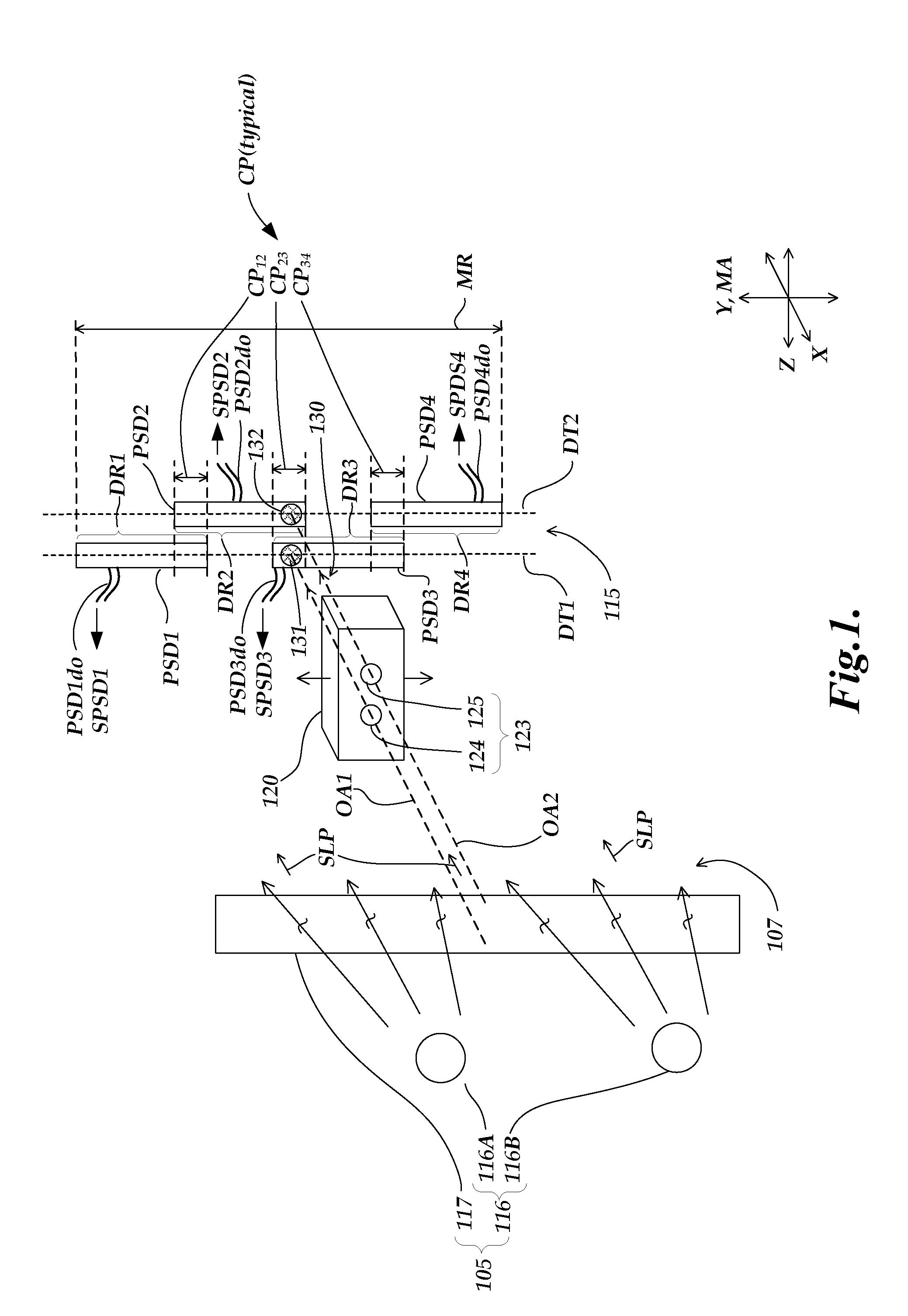
[0023]FIG. 1 is an exploded schematic isometric view diagram of a position sensing device 100 including features of the invention. The position sensing device 100 comprises a light source arrangement 105, a moving aperture arrangement 120, and a multiple position sensitive detector (PSD) arrangement 115. FIG. 1 shows an orthogonal X, Y, Z coordinate system for reference. A measuring axis direction MA of the device 100 is parallel to the Y axis direction, and the moving aperture arrangement 120 is constrained to move along the measuring axis direction MA. In the embodiment shown in FIG. 1, an optical axis OA of an aperture configuration 123 included on the moving aperture arrangement 120 may be approximately perpendicular to the measuring axis direction MA, and the X axis direction may be parallel to the optical axis OA. A sensing surface plane of the multiple PSD arrangement 115 may be approximately parallel to the Y-Z plane.

[0024]The light source arrangement 105 comprises a light g...

second embodiment

[0035]FIG. 3 is an exploded schematic isometric view diagram of a position sensing device 300 including features of the invention. Elements with 3XX series numbers in FIG. 3 that have the same “XX” suffix as 1XX series numbers in FIG. 1 may designate similar or identical elements unless otherwise indicated. Thus, the operation of the position sensing device 300 may generally be understood by analogy with FIG. 1, and only certain aspects of operation will be described here.

[0036]The position sensing device 300 comprises a light source arrangement 305, a moving aperture arrangement 320, and a multiple PSD arrangement 315. The light source arrangement 305 comprises a light generating portion 316 and may comprise a diffuser 317. In contrast to the embodiment of FIG. 1, the light source arrangement 305 is arranged to radiate source light 307 generally along the direction of a source light path SLP which is parallel to the measuring axis direction MA. This configuration allows it to be fi...

third embodiment

[0040]FIG. 4 is an exploded schematic isometric view diagram of a position sensing device 400 including features of the invention. Elements with 4XX series numbers in FIG. 4 that have the same “XX” suffix as 3XX series numbers in FIG. 3 may designate similar or identical elements unless otherwise indicated. Thus, the operation of the position sensing device 400 may generally be understood by analogy with FIG. 3, and only certain aspects of operation will be described here.

[0041]The position sensing device 400 comprises a light source arrangement 405, a moving aperture arrangement 420, and a multiple PSD arrangement 415. The light source arrangement 405 comprises a light generating portion 416 and a second turning minor 419. The light source arrangement 405 is arranged to radiate source light 407 from the second turning minor 419 along the direction of a source light path SLP which is parallel to the measuring axis direction MA, allowing it to be fixed relative to the multiple PSD ar...


PUM


Abstract

A position sensing device having a high range to resolution ratio comprises a light source arrangement, a moving aperture arrangement and a multiple position sensitive detector (PSD) arrangement. The multiple PSD arrangement comprises a plurality of position sensitive detectors arranged along at least two detection tracks along a measuring axis. Each of the plurality of position sensitive detectors shares a common portion of a total measuring range along the measuring axis with an adjacent position sensitive detector which is on a different detector track. The total measurement range is larger than the detector range of each of the position sensitive detectors.

Description

FIELD OF THE INVENTION[0001]The present invention relates to displacement sensors, and more particularly, to a displacement sensing configuration that generates desirable displacement signals having a high range to resolution ratio using position sensitive photodetectors.BACKGROUND OF THE INVENTION[0002]In some applications, it is desirable to provide an optical displacement sensor which provides a linear displacement signal, in a manner analogous to that of LVDT-type sensors. One prior art system of this type is disclosed in U.S. Pat. No. 4,338,722 (the '722 patent), issued to Delmas, which is hereby incorporated by reference in its entirety. The '722 patent discloses a sensor with a light source, a detector comprising two photoreceiver detectors, and a moving stem with an opening to transmit light from the light source to the detectors. The moving stem slides between two guides. A cover over the opening on the moving stem is designed to be substantially symmetrical with the contac...

Claims


Application Information

Patent Timeline
IPC IPC(8): G01B11/14
CPCG01D5/34746G01B11/14
Inventor ATHERTON, KIM
Owner MITUTOYO CORP
Why Eureka
Try Eureka