Camera device with reduced size

a camera device and size reduction technology, applied in the field of camera devices, can solve the problems of unavoidable increase in the size of the camera device, blocking driver's and passenger's views, etc., and achieve the effect of improving the usability of the camera device and adjusting the optical axis angle of the imaging lens

Inactive Publication Date: 2012-10-18
BEAT SONIC
View PDF8 Cites 73 Cited by
  • Summary
  • Abstract
  • Description
  • Claims
  • Application Information

AI Technical Summary

Benefits of technology

[0015]In further another embodiment, the camera housing includes a potion thereof which is located opposite the imaging lens and to which a nut member is fixed. Since the nut member is fixed to the camera housing, the camera body fitted in the socket is rotated using a tool when the nut member is turned by a tool such as a spanner or wrench. This can render the optical axis angle adjustment of the imaging lens easier although the camera housing is formed into the substantially spherical shape.
[0016]In further another embodiment, the bracket has a bottom formed with an adhesive layer. Since the adhesive layer is formed on the bottom of the bracket, the camera body can be installed by adhering the bracket onto a front or rear window glass of the vehicle. This can improve the usability of the camera device.

Problems solved by technology

Accordingly, an increase in the size of the camera device is unavoidable.
This results in blocking driver's and passenger's views by the camera device as well as defiling vehicle interior.

Method used


Image

  • Camera device with reduced size
  • Camera device with reduced size
  • Camera device with reduced size

Examples


first embodiment

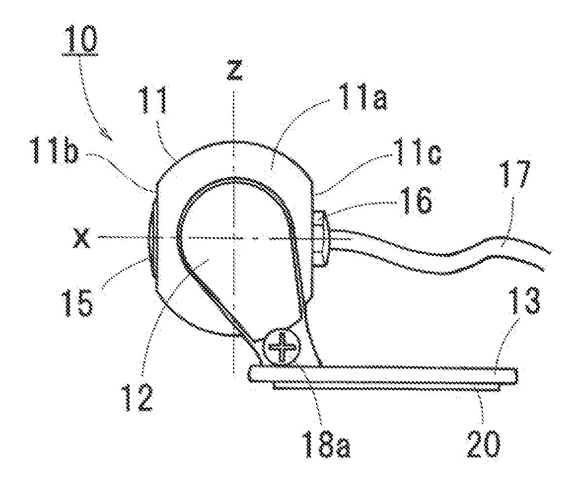
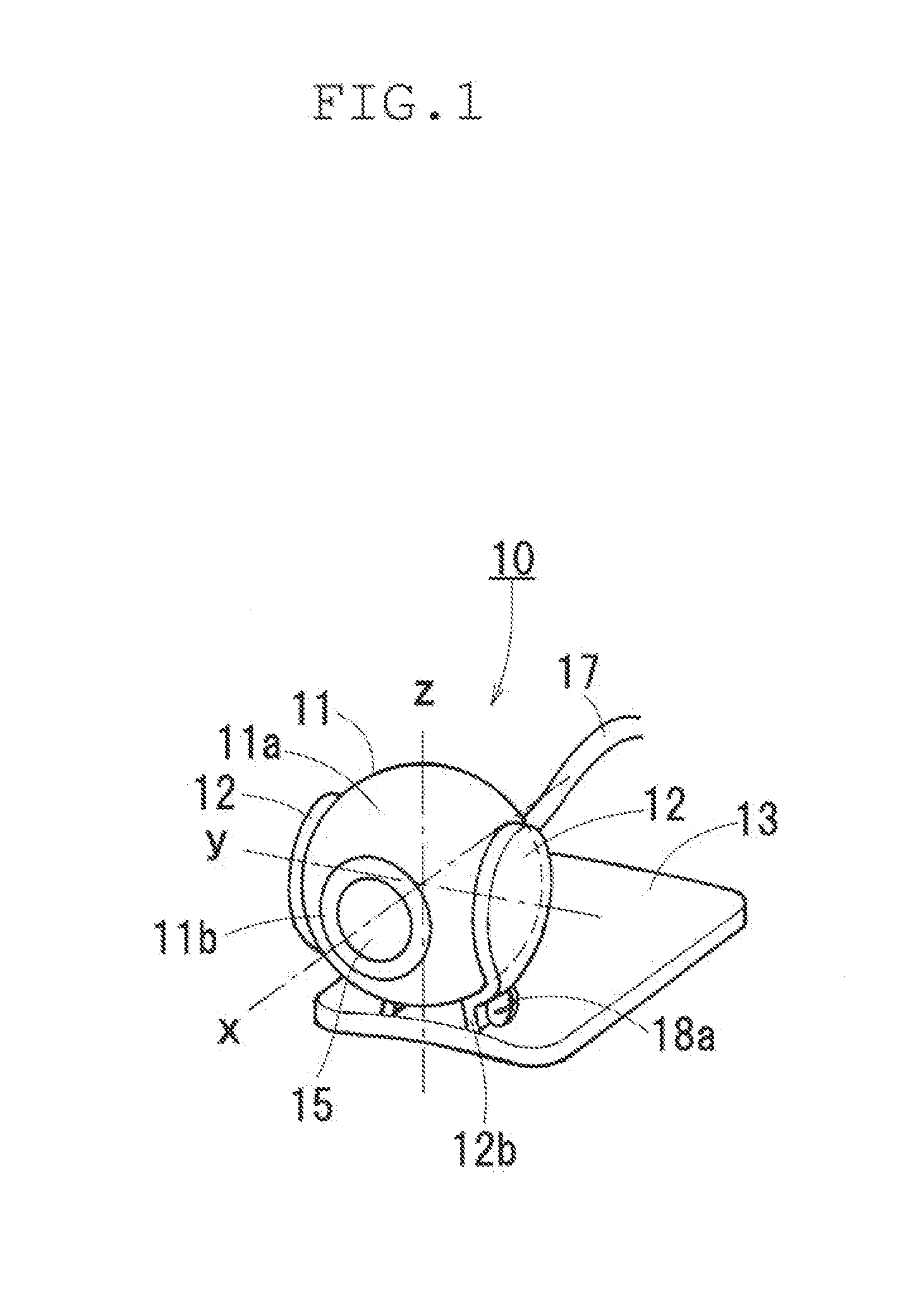
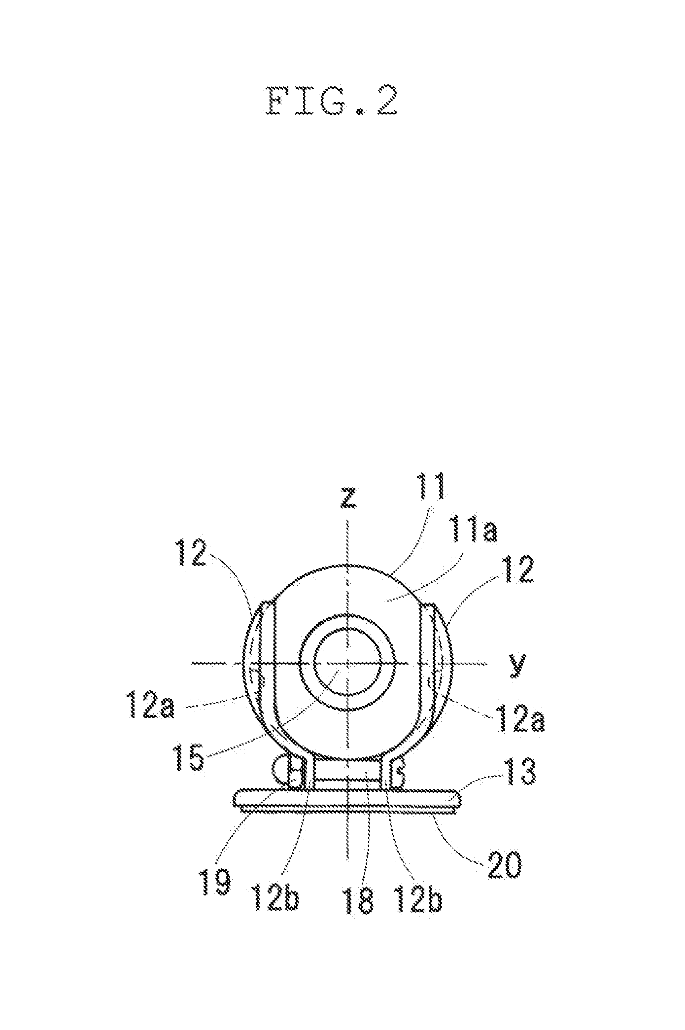
[0029]Embodiments will be described with reference to the accompanying drawings. Referring to FIGS. 1 to 4, a camera device 10 is shown. The camera device 10 includes a camera body 11, a socket including a pair of right and left arms 14 and a bracket 13. The camera body 11 includes a substantially spherical camera housing 11a which has a flat front end surface 11b formed by cutting a part of a sphere and a flat rear end surface located opposite the front end surface and formed by cutting another part of the sphere. An imaging lens is exposed in the front end surface. A nut 16 is fixed to the rear end surface of the camera housing 11a. A cord 17 is drawn through the nut 16 outside the camera housing 11a. The camera body 11 is electrically connected via the cord 17 to a display device or a video device each of which displays a video image obtained by the camera body 11.

[0030]The arms 12 constituting the socket are fixed to the bracket 13 so as to be spaced from each other at opposite...

third embodiment

[0042]When the camera device 60 of the third embodiment is installed on a wall 74 of a residential building, the camera body 60 is fitted into the socket 62 so that the imaging lens 65 of the camera body 60 is exposed through the distal end opening 62a of the socket 62, as shown in FIG. 12. The screw 75 is screwed through the through hole 63c so that the bracket 63 is fixed to the wall 74. The cord 67 is dawn through the cord groove 63d outside the bracket 63.


PUM


Abstract

A camera device includes a camera body including a camera housing which is formed into a substantially spherical shape, a bracket fixable to a vehicle, and a socket provided on the bracket into which a spherical portion of the camera housing is fittable. The camera body includes an imaging lens which is exposed from the socket. The spherical portion of the camera housing is fitted into the socket so that the imaging lens has an optical axis a direction of which is adjustable in a vertical direction and in a right-left direction relative to the socket.

Description

CROSS-REFERENCE TO RELATED APPLICATIONS[0001]This application is based upon and claims the benefit of priority from Japanese Patent Application No. 2011-091762 filed Apr. 18, 2011 the entire contents of which are incorporated herein by reference.BACKGROUND[0002]1. Field[0003]Embodiments described herein relate to a camera device, and more particularly to a camera device suitable to be mounted on vehicles by a customer / user installation manner.[0004]2. Related Art[0005]Japanese Patent Application Publication No. JP-A-2010-254078 discloses a vehicle-mounted customer / user installed camera device comprising a camera body, a holder, a ball joint and a bracket. The holder is fixed to an upper surface of the camera body, and the ball joint is accommodated in the holder. The bracket is mounted on the ball joint.[0006]The bracket is fixed to a vehicle so that the camera device is mounted on the vehicle. The bracket is connected to the ball joint accommodated in the holder. Since the camera b...

Claims


Application Information

Patent Timeline
Patent Type & Authority Applications(United States)
IPC IPC(8): G03B17/56
CPCB60R11/04B60R2011/0024B60R2011/0026F16M11/14B60R2011/0063G03B17/02G03B17/561B60R2011/0033
Inventor TOTANI, TSUTOMU
Owner BEAT SONIC
Why Eureka
Try Eureka