Fluid power helical rotary actuator

Active Publication Date: 2012-10-18
ROSENBOOM MACHINE & TOOL
View PDF8 Cites 7 Cited by
  • Summary
  • Abstract
  • Description
  • Claims
  • Application Information

AI Technical Summary

Benefits of technology

[0011]It is another object, feature, and/or objective of the present invention to provide an improved helical rotary actuator that increases the working area of the actuator.
[0012]It is another object, feature, and/or advantage of the present invention to provide an improved helical rotary actuator that produces a greater torque output without increasing the size of the actuator.
[0013]It is another object, feature, and/or advantage of the present invention to provide an improved helical rotary actuator that uses a shaft with the same diameter for the piston sleeve and the output portions.
[0014]It is another object, feature, and/or advantage of the pr

Problems solved by technology

Problems do exist with standard helical rotary actuators.
Therefore, the amount of torque output is limited by the diameter of the housing itself.
This mean

Method used


Image

  • Fluid power helical rotary actuator
  • Fluid power helical rotary actuator
  • Fluid power helical rotary actuator

Examples


Embodiment Construction

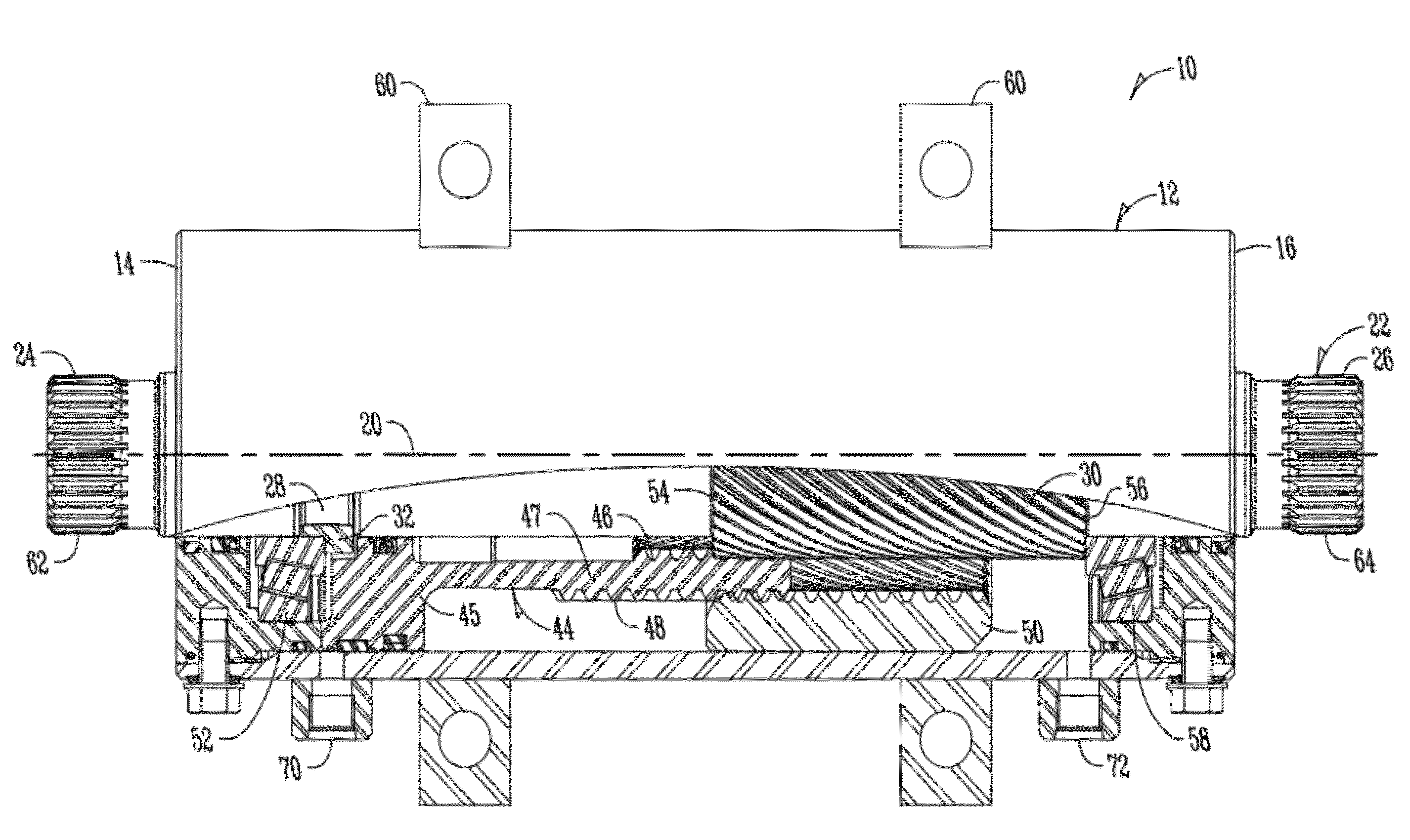
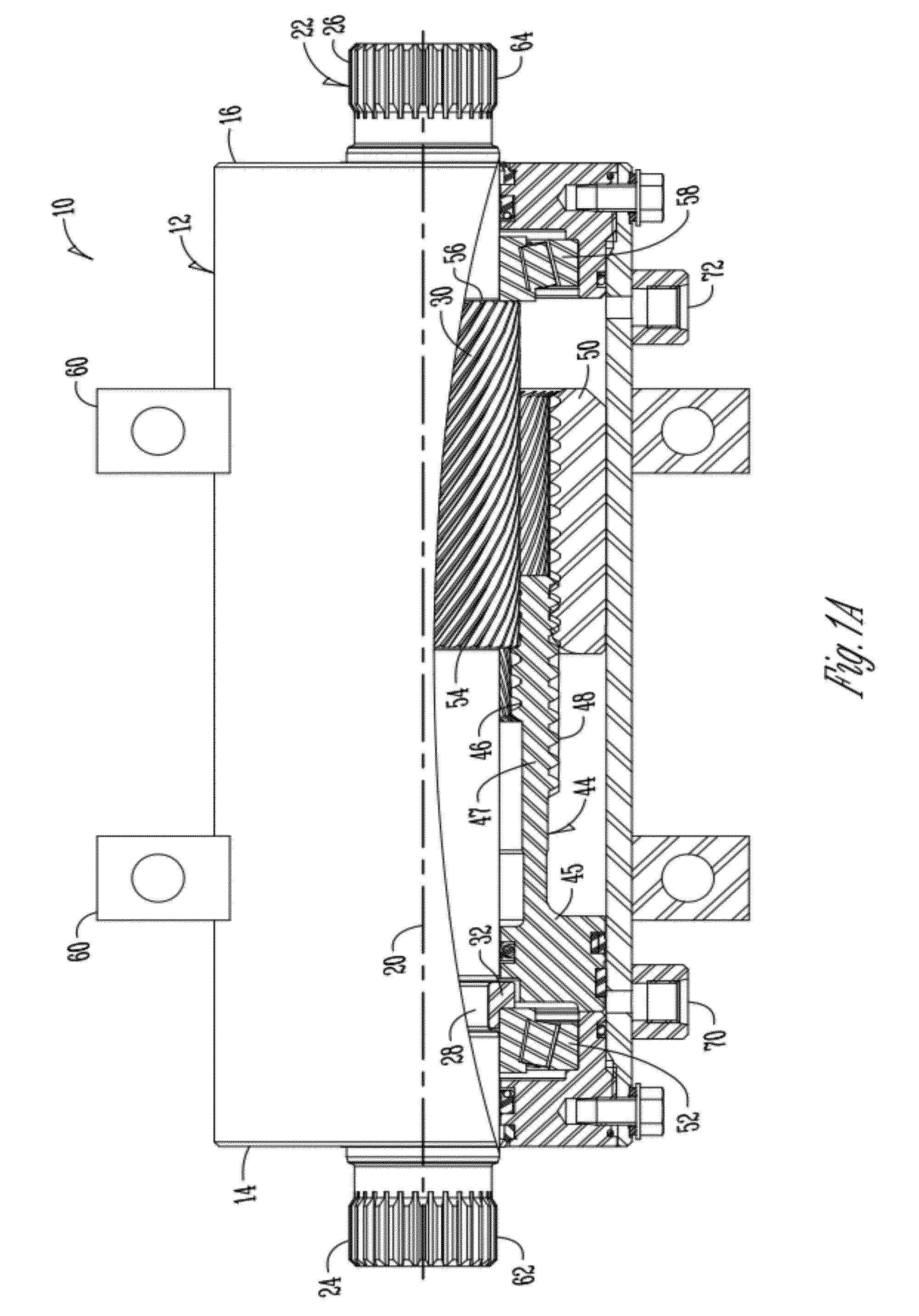
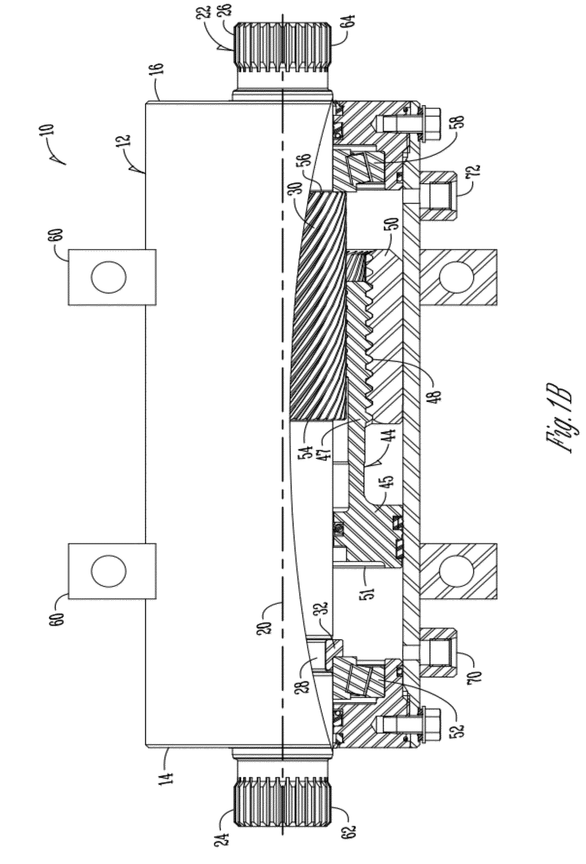
[0028]FIGS. 1A-1C show multiple views of the helical rotary actuator according to the present invention. FIGS. 1A-1C are partial sectional views showing an actuator 10 that is fluid powered with a piston sleeve 44 in three working positions. The location of the piston sleeve 44 relates to a generally rotational output for the actuator 10.

[0029]The fluid powered helical rotary actuator 10 of the present invention includes a housing 12. The housing is generally cylindrically shaped and includes a longitudinal axis 20 there through. The housing 12 further comprises a first end 14 and a second end 16. An interior wall 18, which is also cylindrically shaped, is part of the housing as well. Located within the housing and generally coaxial with the longitudinal axis 20 is a shaft 22. The shaft is rotatable within the housing 12 and includes a first output end 24 and a second output end 26 extending from opposite sides of the housing 12. However, it should be noted that only one output end ...


PUM


Abstract

A fluid-powered, helical rotary actuary is provided. The actuary includes a housing, a shaft with output ends positioned in the housing, and a piston sleeve surrounding the shaft and also positioned within the housing. The shaft includes a groove for receiving a collar. The collar creates a false shoulder such that the shaft is able to have the same diameter along the length of the shaft, thus allowing for a larger working area and more torque output density. The actuary also includes a support ring positioned on the shaft near the splined portion of the output end. The support ring is used to stabilize the attachment of an external member, and also to protect the shaft from damage caused by the splined receiving portion of the external member, or hub.

Description

FIELD OF THE INVENTION[0001]The present invention relates generally to rotary actuators. More specifically, but not exclusively, the invention relates to an improved fluid power helical rotary actuator having an output shaft for providing rotational motion to an attached component and / or assembly.BACKGROUND OF THE INVENTION[0002]Rotary actuators produce oscillating power by rotating an output shaft through a fixed arc. They are compact, simple, and efficient. They produce high instantaneous torque in either direction and require only a small space and simple mountings.[0003]The helical-spline actuator has a long, slender configuration and uses a sliding helical splined gear operating concept to convert linear piston motion into shaft rotation. It is composed of a cylindrically shaped housing and two moving parts: the shaft and the annular piston sleeve. Helical spline teeth machined on the shaft engage a matching complement of splines on the inside diameter of the piston. The outsid...

Claims


Application Information

Patent Timeline
IPC IPC(8): F01C21/00
CPCF04B9/02F04B53/14F04B9/047
Inventor ROSENBOOM, DARIN MICHAELBOLKEMA, RYAN LEEVAN REGENMORTER, DANIEL JON
Owner ROSENBOOM MACHINE & TOOL
Why Eureka
Try Eureka