Method for detecting a boundary crossing

Active Publication Date: 2012-10-18
KAPSCH TRAFFICCOM AG
View PDF1 Cites 23 Cited by
  • Summary
  • Abstract
  • Description
  • Claims
  • Application Information

AI Technical Summary

Benefits of technology

[0005]The present invention is directed to a method for detecting a boundary crossing of an object on a digital road ma

Problems solved by technology

All of these known methods have the disadvantage that they require very elaborate calculations and are thus ill-suited for real-time implementations on OBU processors with limited computational power, or due to position det

Method used


Image

  • Method for detecting a boundary crossing
  • Method for detecting a boundary crossing
  • Method for detecting a boundary crossing

Examples


Example

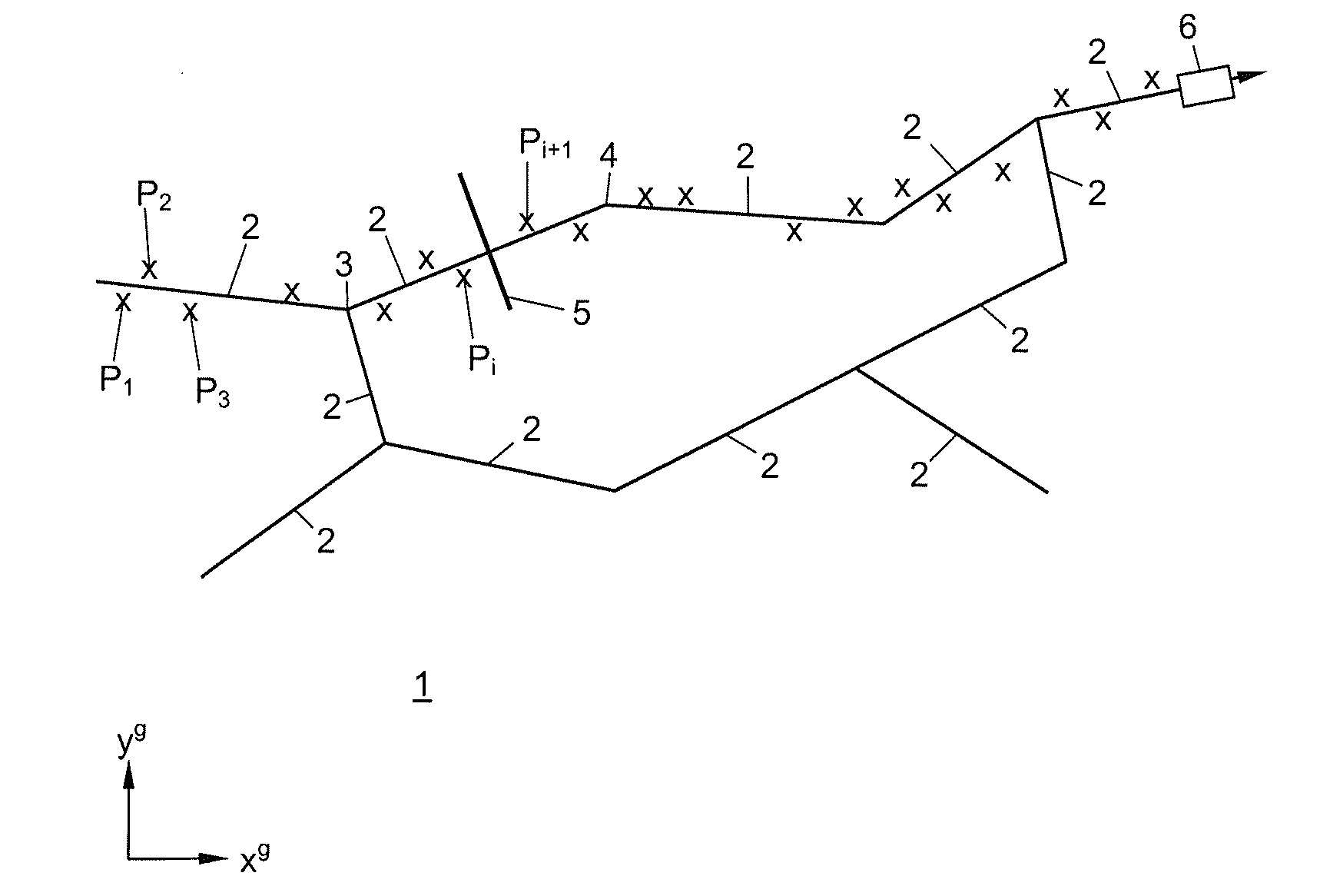
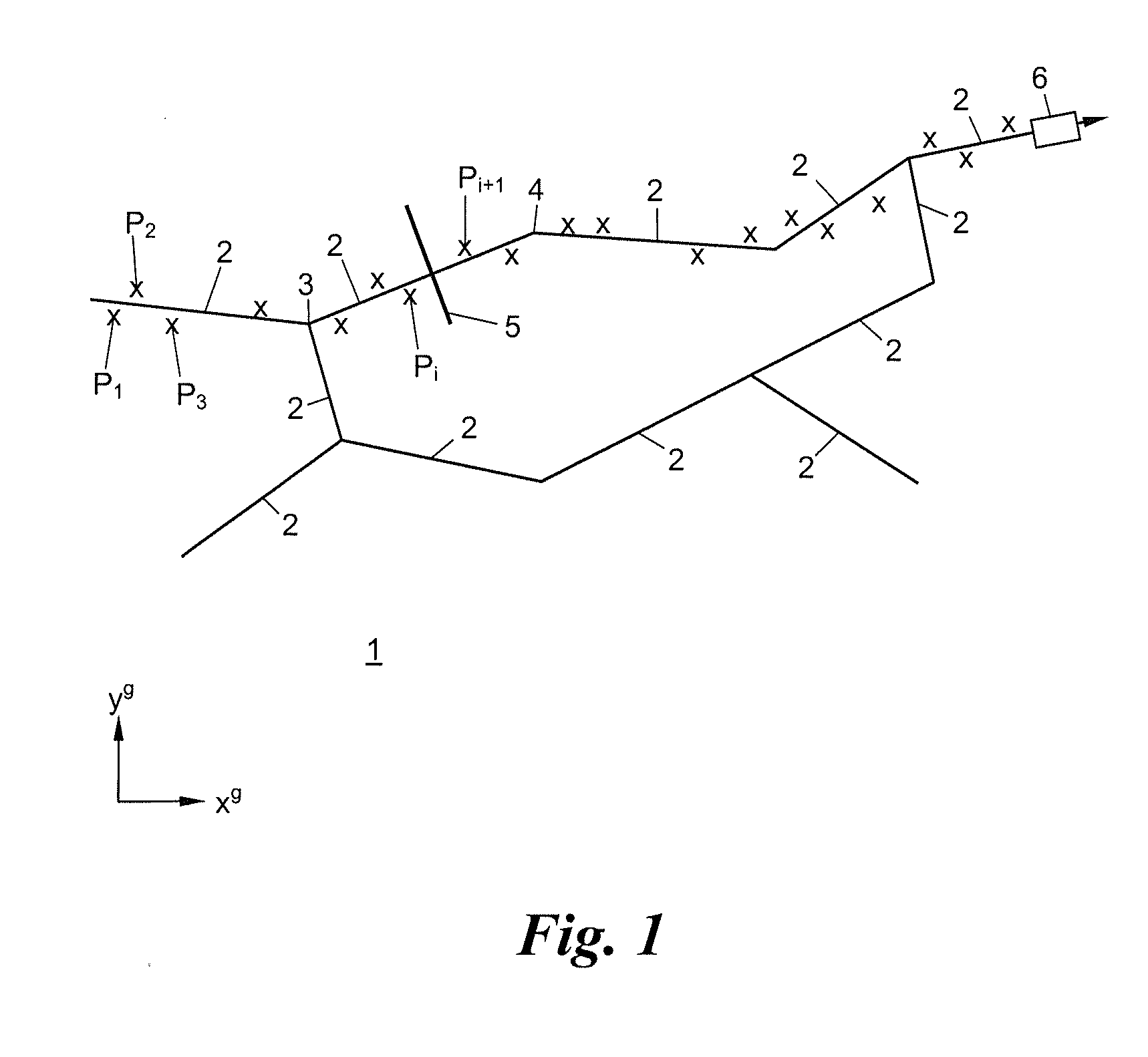
[0015]FIG. 1 shows a cutout of a digital road map 1 with a plurality of road segments 2 that form a road network. The road segments 2 are vectorized and each segment is defined by its beginning or ending points 3, 4, in a global coordinate system xg / yg of the road map 1, as known in the art.

[0016]At least one virtual boundary 5 is intersected by one of the road segments 2. The virtual boundary 5 can also lie at the beginning or endpoint 3, 4 of a road segment 2, i.e., at the connection point of two or more road segments 2. In this exemplary case, the boundary 5 is assigned to one of the road segments 2.

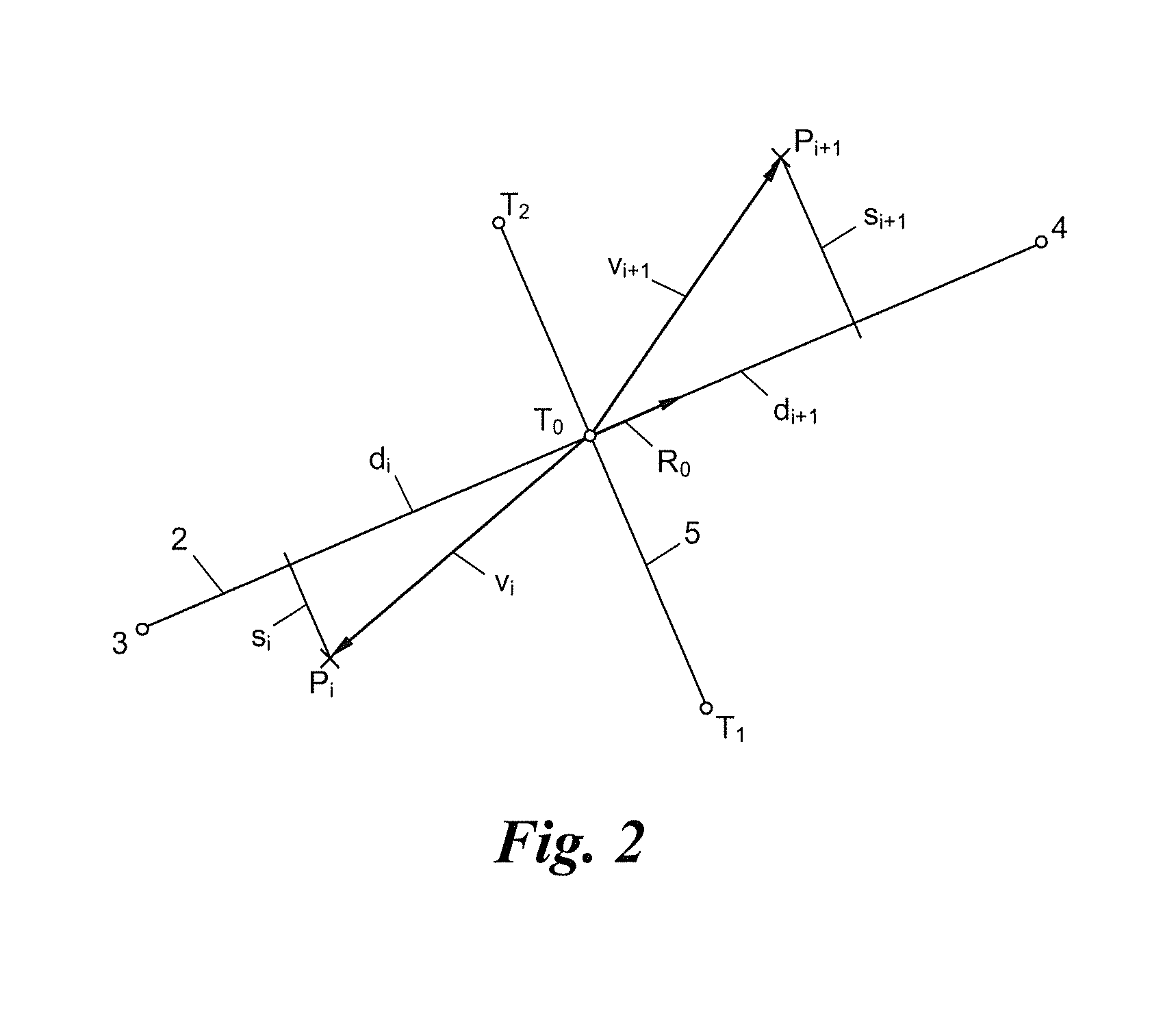
[0017]The boundary 5 can be defined as a vectorized path with a beginning point T1 and an end point T2, from which its intersection point T0 with the crossing road segment 2 can be determined. The boundary 5 can also be defined directly as the intersection point T0.

[0018]The movement of an object 6, such as a vehicle, that continuously determines position fixes in the global coordinat...


PUM


Abstract

Method for detecting a boundary crossing of an object, the movement of which is represented by a sequence of positions on a digital road map ith vectorized road segments and at least one boundary, the method comprising: determining an intersection of the boundary with a road segment and a reference direction in the orientation of this road segment, successively projecting vectors, each determined between one of the positions and the intersection point, onto the reference direction, in order to obtain a sequence of projections, and detecting a boundary crossing if a change of direction or sign occurs in the sequence of projections.

Description

CROSS-REFERENCE TO RELATED APPLICATION(S)[0001]This application claims priority to European Patent Application No. 11 450 051.5, filed on Apr. 15, 2011, the contents of which are hereby expressly incorporated by reference.FIELD OF THE INVENTION[0002]The present invention relates to a method for detecting a boundary crossing of an object having its position represented by a sequence of positions on a digital road map with vectorized road segments and at least one boundary.BACKGROUND[0003]Detecting a boundary crossing on a digital road map is of crucial importance for electronic toll systems based on global satellite navigation systems (GNSS) such as GPS, GLONASS, Galileo, etc. In such GNSS toll systems, vehicle-based onboard units (OBUs) continuously determine their own positions (“position fixes”), by of satellite navigation systems. Then positions are then compared decentrally in the OBUs or centrally in one or more server computers of the road toll system—to road segments of a dig...

Claims


Application Information

Patent Timeline
IPC IPC(8): G06F17/00
CPCG08G1/207G01C21/30
Inventor WEIMANN, FRANZ
Owner KAPSCH TRAFFICCOM AG
Why Eureka
Try Eureka