
Relative position/posture measuring system

Active Publication Date: 2005-09-15
SONY COMPUTER ENTERTAINMENT INC
View PDF4 Cites 16 Cited by
  • Summary
  • Abstract
  • Description
  • Claims
  • Application Information

AI Technical Summary

Benefits of technology

[0011] An object of the present invention is to provide a relative position / posture measuring system little affected by noises, capable of executing a quick rate action and being fully endurable in practical use for measurement of a position and a posture of an object in virtual reality.
[0012] To achieve the object described above, the present invention provides a relative position / posture measuring system little affected by noises and capable of executing a quick rate action by employing an M-sequential demodulation system for measuring a relative position and a posture between two objects using a magnetic field amplitude.
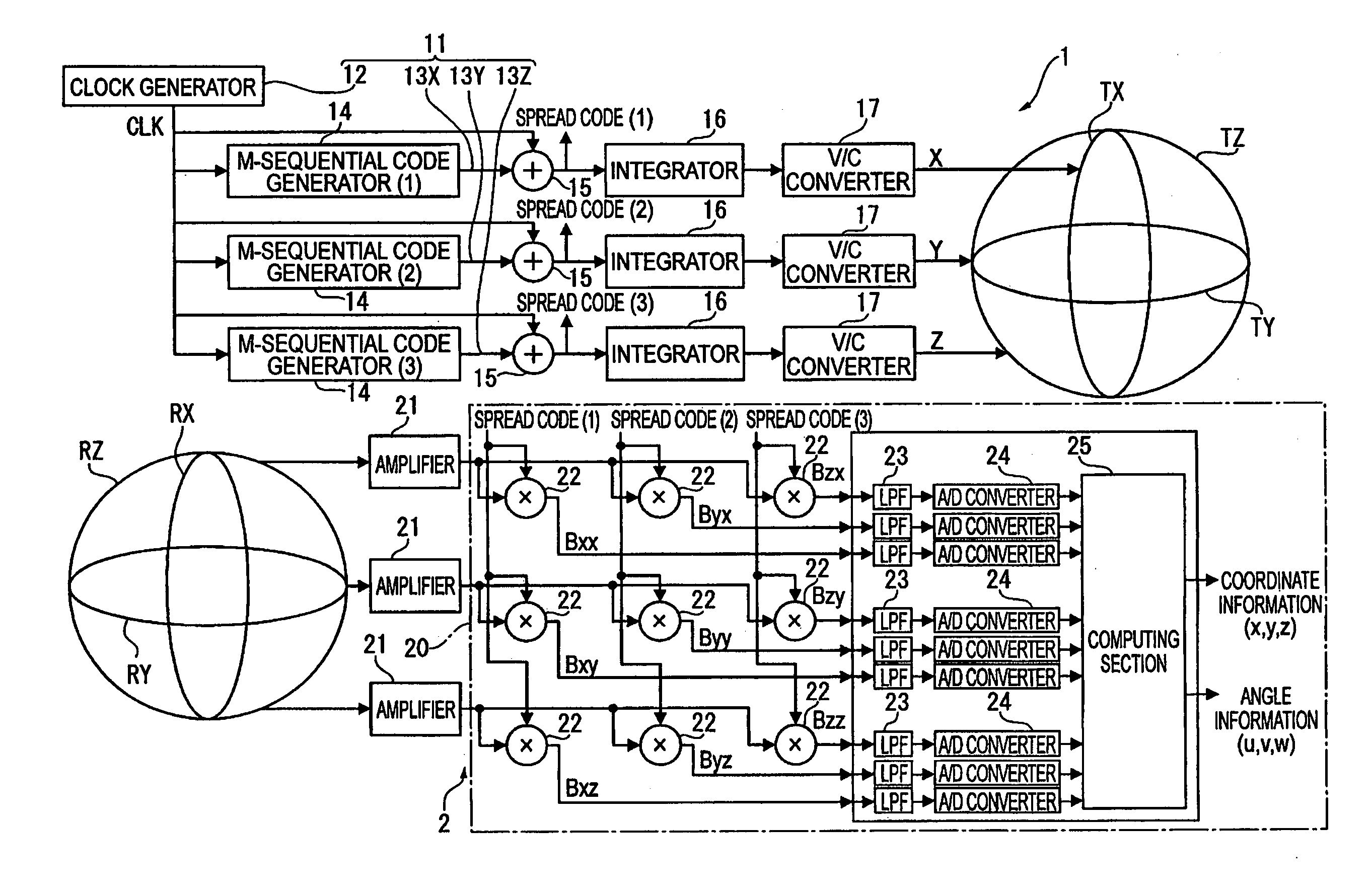
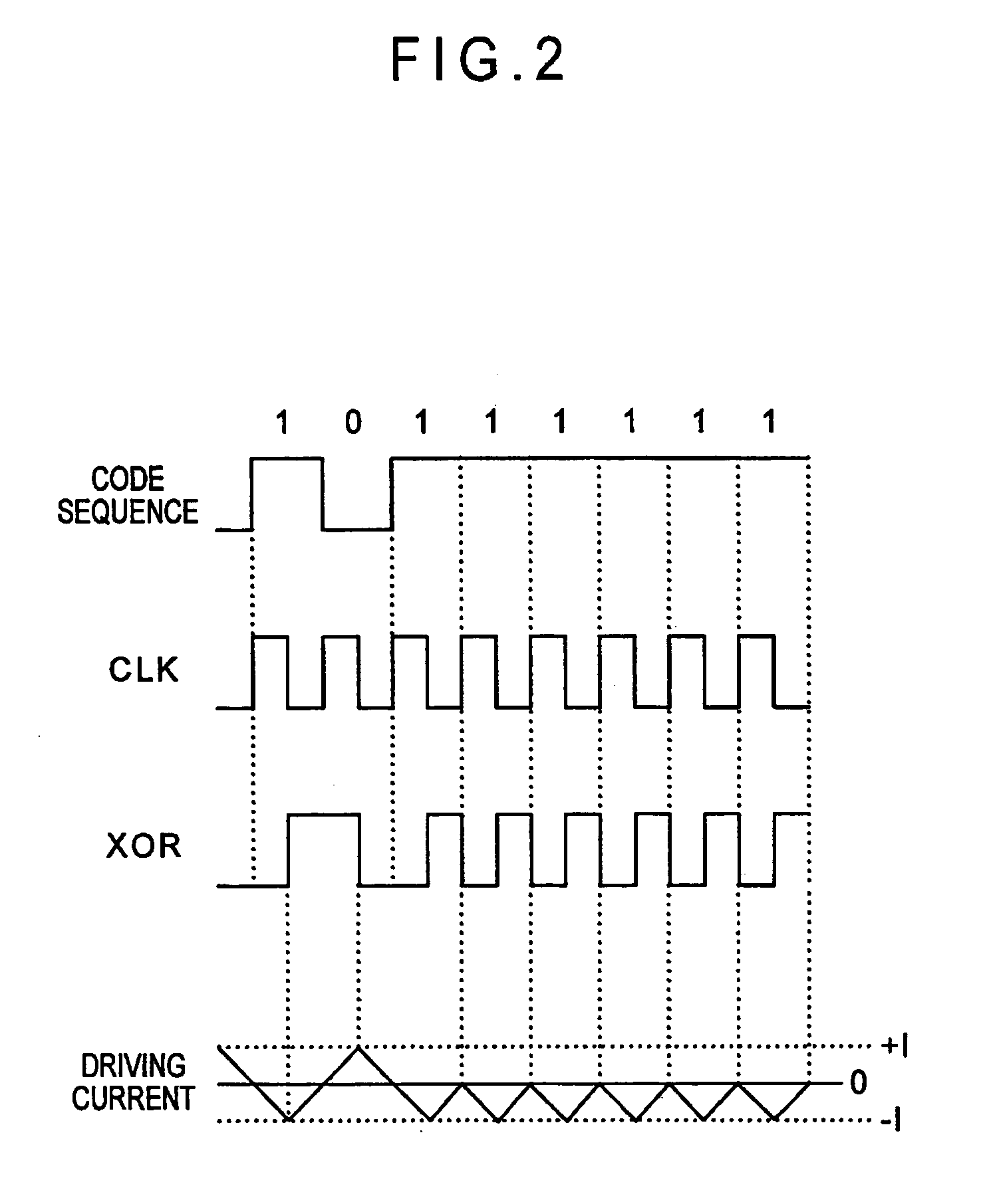
[0016] With the present invention, by converting different code sequences generated by the M-sequential code generator to spread code and also by generating a driving current for each transmission coil based on a voltage waveform obtained by integrating the spread code, the magnetic field detector can detect a magnetic field detection value as a change in the magnetic flux density when a change occurs in relative positions between and relative postures of the magnetic field generator and the magnetic field detector. Therefore, by reversely spreading the magnetic field detection value with the computing unit, the state prior to integration by the integrator can be detected, so that the relative positions between and relative postures of the magnetic field generator and the magnetic field detector can be computed.
[0017] Further, by employing the M-sequential demodulation system as the modulation system, the magnetic field detector can discretely identify and separate each of the magnetic fields generated by the transmission coils, and therefore it is not necessary to output a magnetic field detection value from each transmission coil in the time division mode, and an excellent response and further wideband spreading is executed, so that it is possible to measure relative positions between and relative postures of the two without being affected by noises even when the distance between the magnetic field generator and the magnetic field detector is large.
[0027] Further, by increasing the numbers of transmission coils and receiving coils, more magnetic field detection values can be obtained, so that the number of simultaneous equation as targets for analysis increases, and therefore precisions of the relative positional coordinate information and relative posture information computed as described above can be improved.

Problems solved by technology

The polhemus sensor as disclosed in the Reference has, however, the following problems.
In other words, generation of a magnetic field by each transmission coil is carried out in the time division mode, a long period of time is required for detecting a position and a posture of an object to be measured, and the rate action is disadvantageously delayed.
Further, the communication system using a carrier wave as it is employed, so that the system is weak to noises, and detection of a position is possible within a short distance, and therefore the communication system can not practically be applied as a position measuring system in the virtual reality.
Especially, when the number of channel is increased for more accurately computing a state of the object to be measured, influence by noises becomes disadvantageously larger.

Method used


Image

  • Relative position/posture measuring system
  • Relative position/posture measuring system
  • Relative position/posture measuring system

Examples


Embodiment Construction

)

[0030] An embodiment of the present invention is described below with reference to the related drawings.

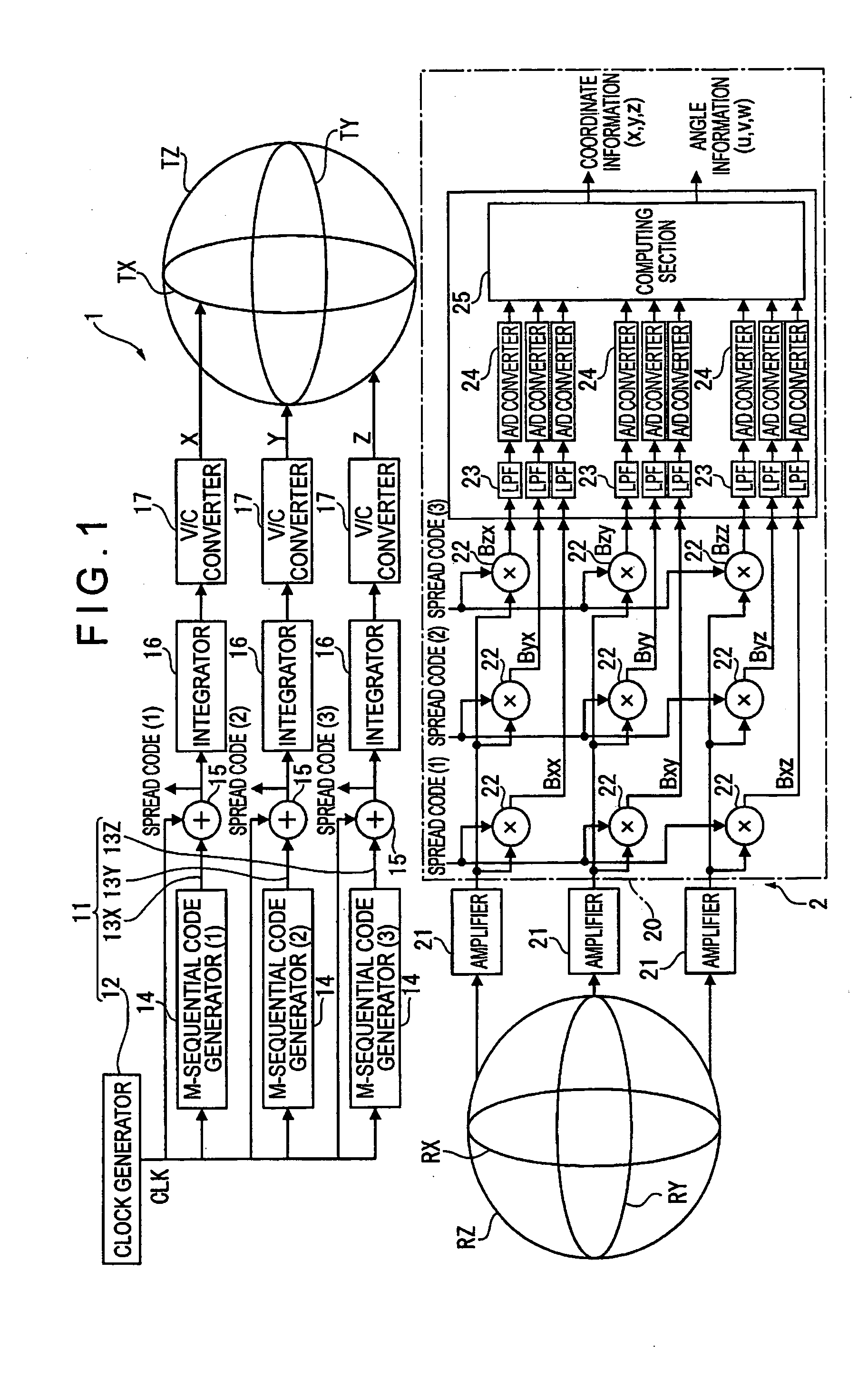
[0031]FIG. 1 shows a relative position / posture measuring system according to the embodiment of the present invention, and this relative position / posture measuring system includes a transmission side unit 1 as a magnetic field generator and a receiving side sensor unit 2 including a magnetic field detector.

[0032] The transmission side unit 1 includes three transmission coils TX, TY, TZ arranged orthogonal to the axis X, axis Y, and axis Z within a three-dimensional space and a unit body 11 giving a driving current to the transmission coils TX, TY, TZ.

[0033] Each of the transmission coils TX, TY, TZ generates a magnetic field by making use of electromagnetic induction, and includes a wire wound into a coil having a prespecified diameter with a prespecified number of turns, and for instance, a coil with the diameter of 90 mmΦ and 100 turns may be used. The transmission coils TX, ...


PUM


Abstract

The present invention provides a relative position / posture measuring system for measuring relative positions and relative postures between a magnetic field generator (1) and a magnetic field detector (2) by detecting a change in a magnetic field, in which the magnetic field generator includes a clock generator (12), a plurality of M-sequential code generators (14), a plurality of spread code generators (15), a plurality of integrators (16), and a voltage / current converter (17), and transmission coils TX, TY, TZ generate magnetic fields according to driving currents based on spread code obtained by converting code sequences generated by the M-sequential code generators (14) to spread code with the spread code generators (15). The magnetic field detector (2) reversely spreads received magnetic field detection values to obtain a magnetic field amplitude, and computes relative positions and relative postures of the two from the magnetic field amplitude.

Description

BACKGROUND OF THE INVENTION [0001] 1. Field of the Invention [0002] The present invention relates to a relative position / posture measuring system including a magnetic field generator including a plurality of transmission coils arrayed orthogonal to each other for transmitting a magnetic signal from each transmission coil, a magnetic field detector for receiving a magnetic field generated in each transmission coil as a magnetic field detection value for each transmission coil, and a computing unit for computing a relative distance and a relative posture between the magnetic field generator and the magnetic field detector based on the magnetic field detection value for each transmission coil received by the magnetic field detector. [0003] 2. Description of Related Art [0004] There has been known the Polhemus sensor using a magnetic sensor as a system for measuring a space position of an object to be measured or a posture thereof in the measuring step. [0005] This polhemus sensor is a ...

Claims


Application Information

Patent Timeline
IPC IPC(8): G01C15/00G01B7/00G01B7/14H01F5/00H04B1/707
CPCA63F2300/105G01D5/2086G06F3/0346G01R33/028G01R33/0206
Inventor SHIMIZU, MASAO
Owner SONY COMPUTER ENTERTAINMENT INC
Learn More