
Montgomery multiplication circuit

Active Publication Date: 2012-10-18
RAMBUS INC
View PDF0 Cites 18 Cited by
  • Summary
  • Abstract
  • Description
  • Claims
  • Application Information

AI Technical Summary

Benefits of technology

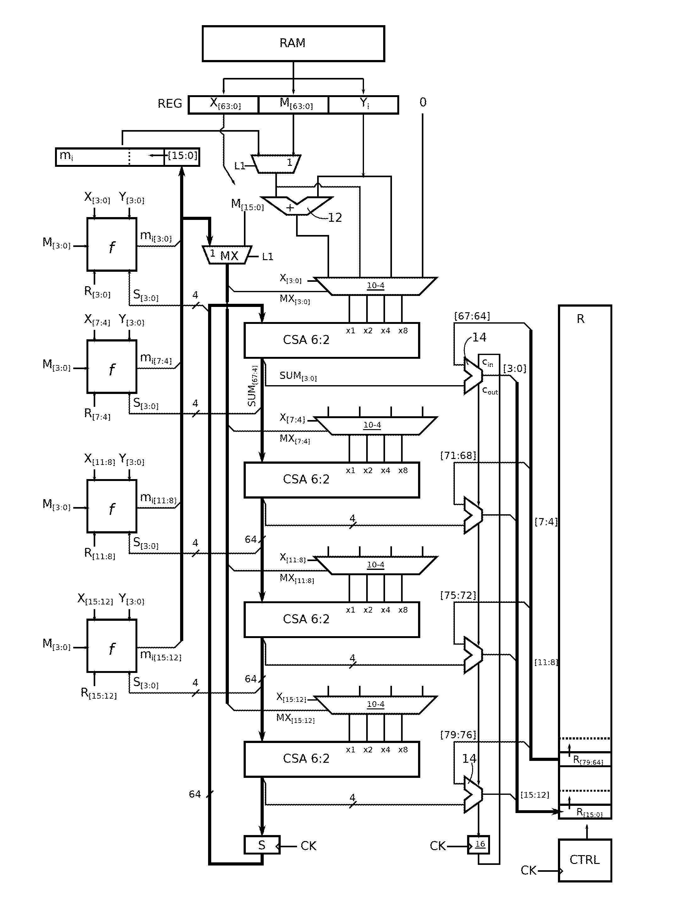
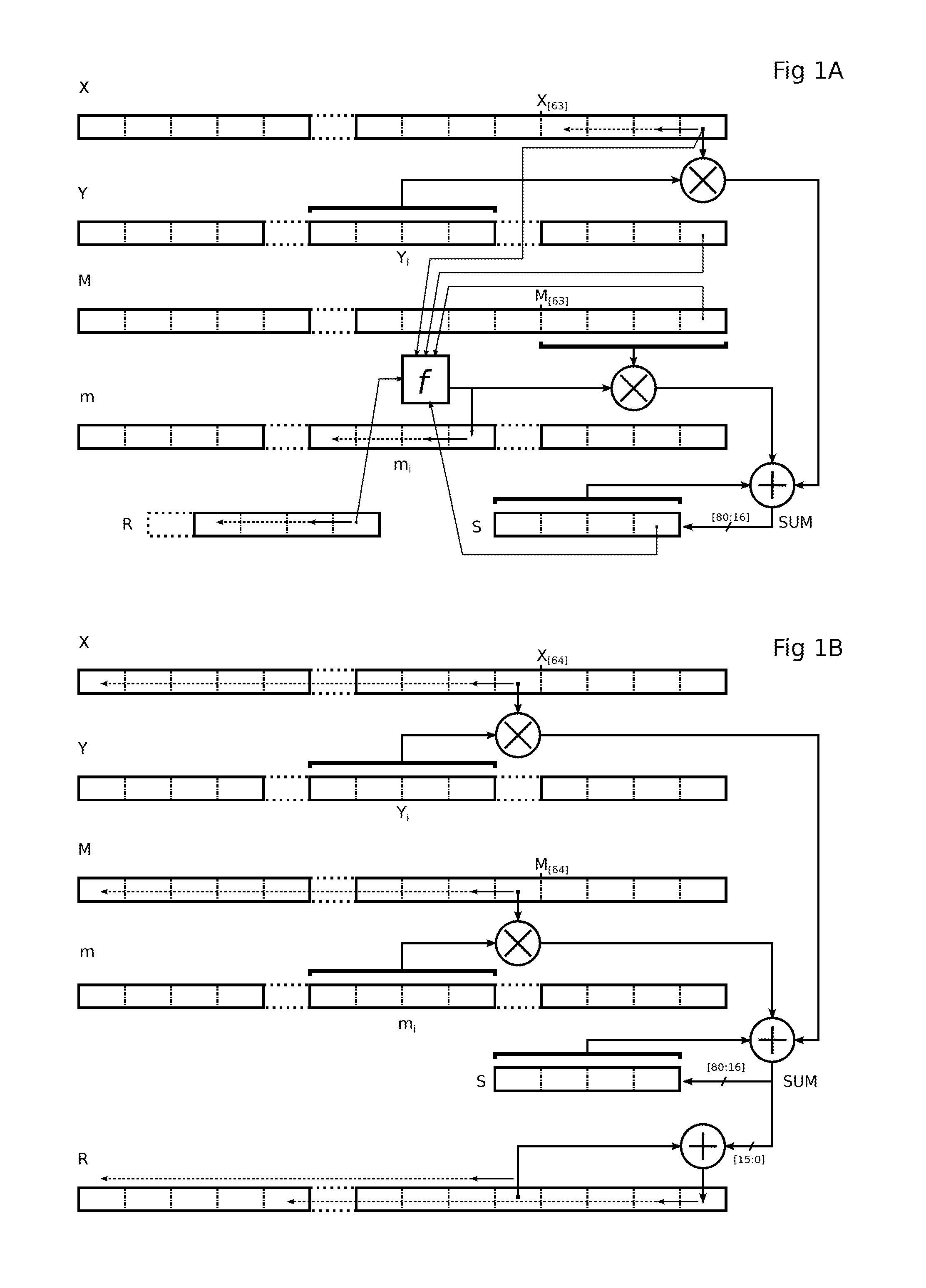
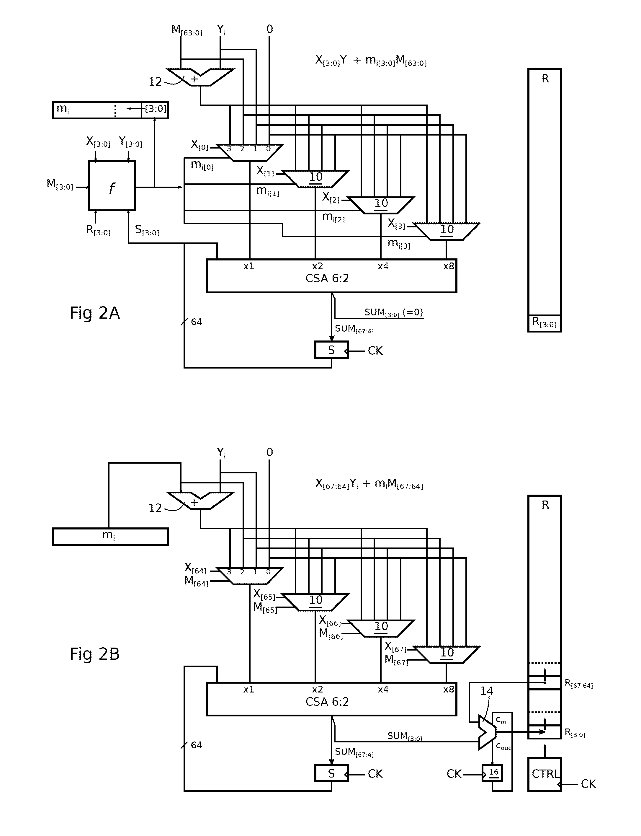
[0032]The system may be applied to the modular product calculation of two L-bit numbers X and Y, wherein the result of the modular multiplication may be defined from a value XY+mM, where M is the modulo, of L bits, and m is an L-bit number found such that this value is divisible by 2L. The circuit is used for the calculation of an intermediate term XYi+miM+R by iterations at the rhythm of a clock, where Yi and mi are the k-bit digits of rank i of numbers Y and m starting from the least significant bits, and R is the sum of the previous terms. The circuit has a first mode where it receives as k-bit operands the number Yi and the k first bits of number M, and as q-bit operands, q bits of number X and q bits of number mi. The system includes a control circuit arranged to select as q-bit operands

Problems solved by technology

A difficulty encountered to implement these calculations on a microprocessor results from the fact that the size of the numbers is too large (for example 512 bits) in relation to the computing capacity of the microprocessor (for example 64 bits).

Method used


Image

  • Montgomery multiplication circuit
  • Montgomery multiplication circuit
  • Montgomery multiplication circuit

Examples


Embodiment Construction

[0040]To accelerate the calculation of a modular multiplication of two numbers whose sizes exceed the computing capacity of the processor, it is wished to improve the efficiency of each intermediate calculation, and to organize the intermediate calculations so that all the cycles of the processor are used.

[0041]The relationship (1) is equivalent to:

R=2−L(XY+mM),   (3)

[0042]where m is an L-bit number found such that the L least significant bits of the sum, coded on 2L bits, are null. In other words, R corresponds to the L most significant bits of the sum.

[0043]By developing the iterative calculations of the relationship (2), the following is obtained:

2LR=XY[0]+m[0]M+2(XY[1]+m[1]M)+22(XY[2]+m[2]M)+…+2L-1(XY[L-1]+m[L-1]M),(4)

[0044]and number m of the relationship (3) reveals to be: m=(m[L−1], m[L−2], . . . m[2], m[1], m[0]).

[0045]An intermediate version of this relationship may be rewritten so that one of the operands of each product, which may be referred to as “digit”, has a size k h...


PUM


Abstract

A circuit for calculating a sum of products, each product having a q-bit binary operand and a k-bit binary operand, where k is a multiple of q,includes a q-input carry-save adder (CSA); a multiplexer (10) by input of the adder, having four k-bit channels respectively receiving the value 0, a first (Yi) of the k-bit operands, the second k-bit operand (M[63:0], mi), and the sum of the two k-bit operands, the output of a multiplexer of rank t (where t is between 0 and q−1) being taken into account by the adder with a t-bit left shift; and each multiplexer having first and second path selection inputs, the bits of a first of the q-bit operands being respectively supplied to the first selection inputs, and the bits of the second q-bit operand being respectively supplied to the second selection inputs.

Description

BACKGROUND OF THE INVENTION[0001]Embodiments of the invention relate to the Montgomery algorithm to execute a modular multiplication, also called Montgomery multiplication, and in particular to an electronic circuit optimized to execute the product.[0002]The Montgomery algorithm is described in “Modular Multiplication Without Trial Division”, Peter Montgomery, Mathematics of Computation, vol. 44, pp. 519-521, 1985. According to the Montgomery algorithm, when it is applied to binary numbers, the following value needs to be calculated:R=XY·2−L mod M   (1)[0003]Where R, X, Y and M are L-bit numbers. M is the modulo; it is odd and higher than X and Y.[0004]This calculation is often used to execute modular exponentiations in encryption, where numbers are “big”, i.e., the L-bit number is of several hundred, for example 512. The algorithm then allows calculations to be simplified by limiting the number of divisions and limiting the size of the intermediate multiplication results to the siz...

Claims


Application Information

Patent Timeline
IPC IPC(8): G06F7/50G06F5/01
CPCG06F7/5275G06F7/728G06F7/5443
Inventor NIEL, MICHAEL
Owner RAMBUS INC
Learn More