Signal transmission systems

a transmission system and signal technology, applied in the field of signal transmission systems, can solve the problems of a 3g network having a significant detrimental effect on the environment, a radiation hazard associated with the increase of power transmission from the antenna, and generally not operator-specific problems

Inactive Publication Date: 2002-06-20
NTL GROUP
View PDF0 Cites 197 Cited by
  • Summary
  • Abstract
  • Description
  • Claims
  • Application Information

AI Technical Summary

Problems solved by technology

However, the GSM hardware such as the Base Transceiver Stations and GSM terminals (or "Mobile Equipment") into which the SIM cards are inserted, is generally not operator-specific and is usable with any GSM network.
A problem with this system is, however, that it is only able to serve a single antenna and a separate fibre optic cable connection is required for each separate antenna 312.
This results in a number of problems.
Installing a 3G network can have a significant detrimental effect on the environment as a large number of antenna sites is required for the smaller, more numerous cells, especially because the required number of sites is multiplied by the number of different network operators (in the UK, five).
A related problem is the possible radiation hazard associated with the increased power transmission from antennas at these sites.
Acquiring sites for these new antennas is expected to be difficult and expensive and, more generally, large capital and operational costs are expected to be associated with 3G networks.
Maintenance of base station equipment for such a large number of cells, and upgrading such networks to provide increased capacity, is also likely to be time consuming and expensive.

Method used


Image

  • Signal transmission systems
  • Signal transmission systems
  • Signal transmission systems

Examples


Embodiment Construction

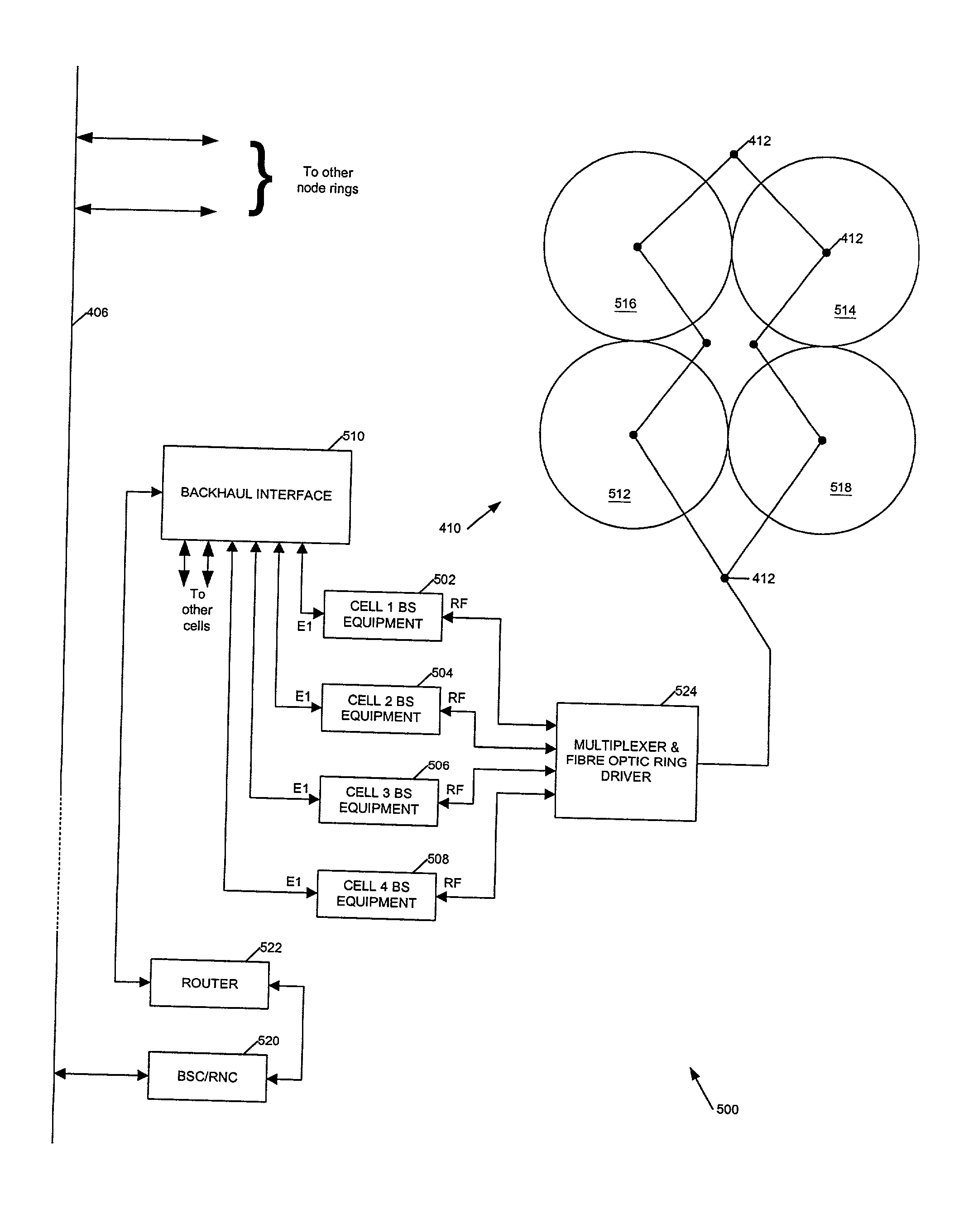
[0077] Referring first to FIG. 3b, this shows a simplified block diagram of a transmitter signal distribution system. In a third generation CDMA-based cellular mobile communications network adjacent cells or cell sectors may operate on the same transmit frequency since mobile communications devices within the cells identify transmissions using the spreading code sequence rather than (or in addition to) the broadband transmit frequency. Thus, in FIG. 3b, Cells 1 to 4 may all be served by a single transmitter, the need for separate cells arising in part because of the difficulties in providing coverage over a geographical area, particularly in urban environments where buildings cause shadowing and signals tend to propagate along the directions of streets. Thus the arrangement of FIG. 3b assists in achieving uniform coverage over an urban or suburban region and, in common with other aspects of the invention outlined above, also reduces the quantity of equipment required at each antenna...


PUM


Abstract

Signal transmission systems for second and third generation mobile communications networks are described. A signal distribution system comprises a plurality of rf transmitters for serving a plurality of network cells. The system is characterised by a multiplexer coupled to the transmitters for multiplexing the transmitter outputs, a signal transporter for transporting the multiplexed signals to each of the network cells, and a multiplexed signal receiver at each cell for selecting and receiving a signal from a transmitter serving the cell. The invention also provides a complementary signal reception system, and corresponding methods. Preferably, the multiplexed signals are transported over a fibre optic network such as an existing cable TV network. The system simplifies the deployment of network infrastructure for third generation mobile communications systems.

Description

[0001] This invention is concerned with the transmission of signals between elements of a cellular communications network, such as a GSM network or an IMT-2000 network. More particularly it relates to the transmission of signals between transmitters and / or receivers serving cells in the network and antennas at the cells themselves. Aspects of the invention provide a system for distributing signals from a plurality of such transmitters to a plurality of cells and a system for receiving signals from a plurality of cells and transmitting these signals to a plurality of receivers.BACKGROUND TO THE INVENTION[0002] FIG. 1 shows an overview of one type of cellular communications network, a GSM (Global System for Mobile communications) network 100. Referring to FIG. 1, a plurality of Base Transceiver Stations (BTS) 102 are coupled to a Base Station Controller (BSC) 104 by digital links 106 across the so-called A.sub.bts interface. Each BTS 102 is provided with an antenna (or set of antennas...

Claims


Application Information

Patent Timeline
Patent Type & Authority Applications(United States)
IPC IPC(8): H04B10/2575
CPCH04B10/25756
Inventor COLE, STEVEN R.CONNOLLY, DAVIDSUMMERS, NIGEL A.
Owner NTL GROUP
Why Eureka
Try Eureka