
Adjustable Grinding Platform and Mounting Assembly

a technology of mounting assembly and adjustable angle, which is applied in the direction of grinding machines, grinding machine components, manufacturing tools, etc., can solve the problems of inability to accurately determine the angle of the platform, and large angle adjustment angle of the protractor

Inactive Publication Date: 2012-10-25
BATTY STUART
View PDF16 Cites 49 Cited by
  • Summary
  • Abstract
  • Description
  • Claims
  • Application Information

AI Technical Summary

Benefits of technology

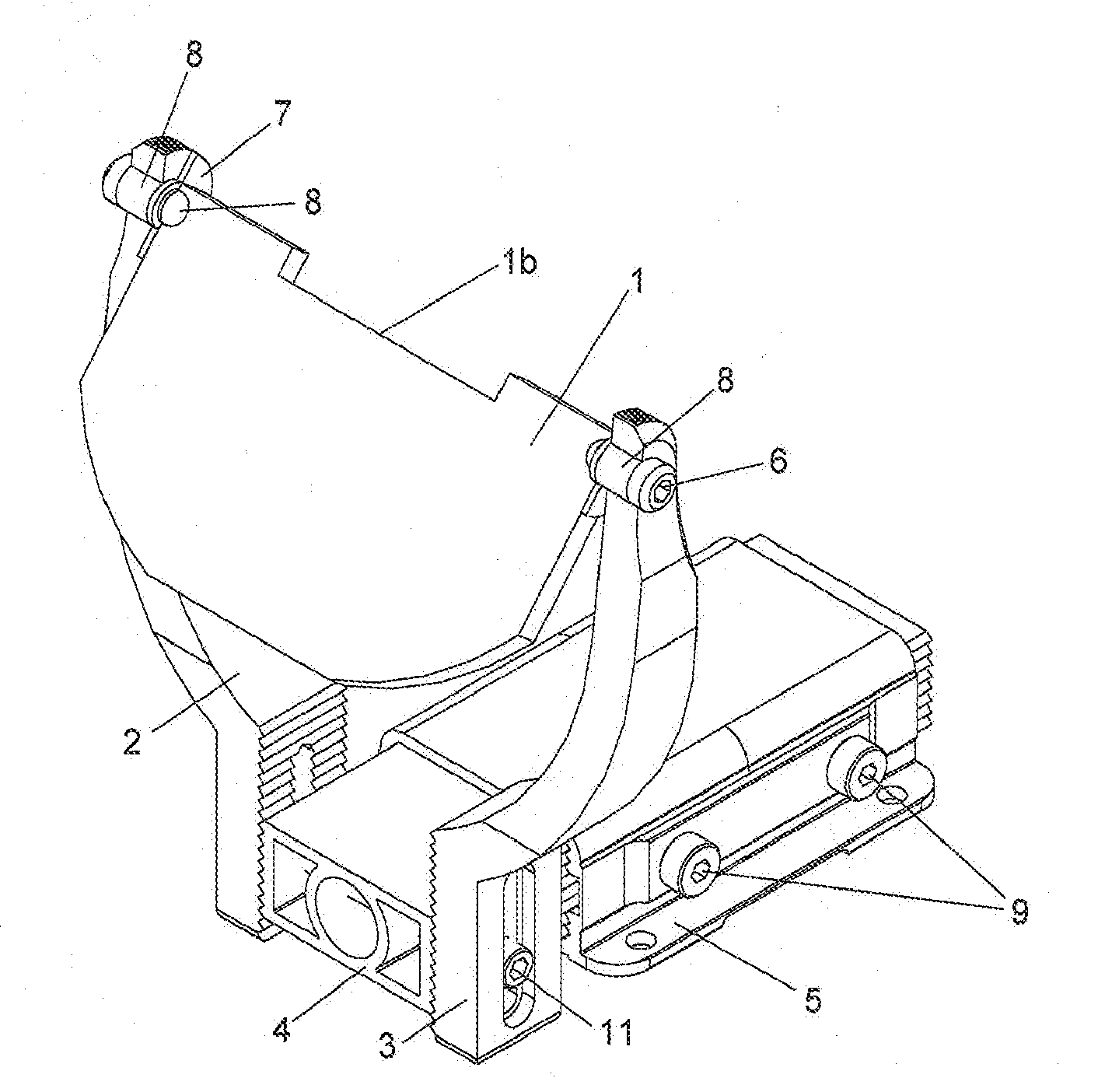
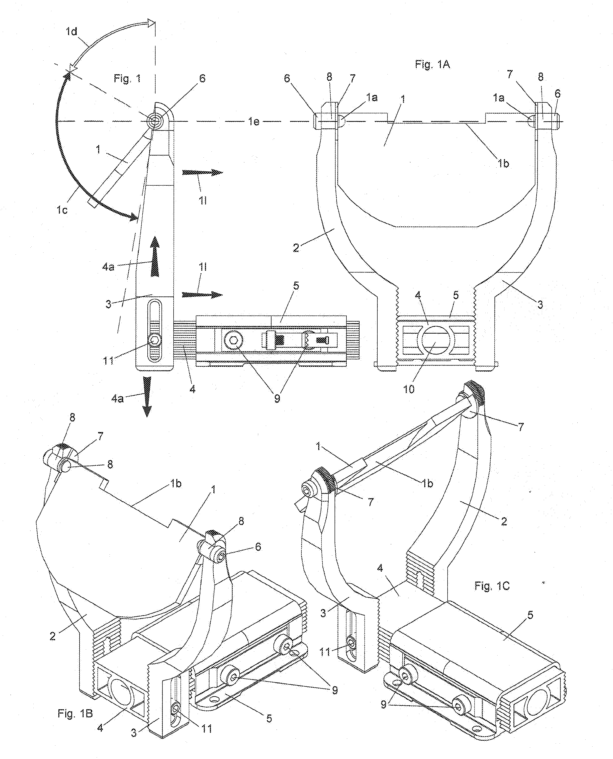
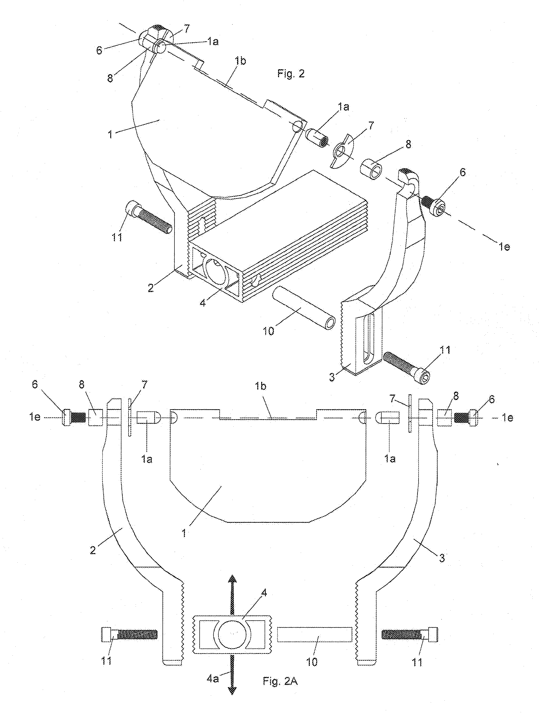
The technical effect of this patent is to create a device for grinding surfaces that can rotate on both flat and curved surfaces while also allowing for precise positioning through pivoting centers and continuous/indexed movements. Additionally, there will be a work rest with accurate angling capabilities and a Vernier scale for further precision.

Problems solved by technology

The technical problem addressed in this patent text relates to accurately measuring the angle at which a wooden tool or other material is being ground down during sharpening procedures. Existing solutions involve trial and error processes, multiple jigs, or expensive and potentially unreliable equipment like digital angle gauges. There is a need for an improved solution that allows for accurate and efficient angling detection without requiring significant setup effort or specialized hardware.

Method used


Image

  • Adjustable Grinding Platform and Mounting Assembly
  • Adjustable Grinding Platform and Mounting Assembly
  • Adjustable Grinding Platform and Mounting Assembly

Examples


Embodiment Construction

[0111]For the purposes of promoting an understanding of the principles of the invention, reference will now be made to the embodiments illustrated in the drawings and specific language will be used to describe the same. However, the illustrated embodiments are merely exemplary and many additional embodiments of this invention are possible. It is understood that no limitation of the scope of the invention is thereby intended. Any alterations and further modifications in the illustrated devices, and such further application of the principles of the invention as illustrated herein are contemplated as would normally occur to one skilled in the art to which the invention relates.

[0112]Unless otherwise indicated, the drawings are intended to be read (e.g., arrangement of parts, proportion, degree, etc.) together with the specification, and are to be considered a portion of the entire written description of this invention. As used in the following description, the terms “horizontal”, “vert...


PUM


Abstract

A grinding platform with an axis of rotation that is on the plane of the abrasive when used with belt grinders and on the plane that is vertical and tangent to the curvature of the abrasive when used with wheel grinders; such grinder having an angle gauge and possibly a vernier scale that allow for accurate determination of the angle of the tool rest in relation to the grinding surface. The grinding platform can also be continuously adjusted horizontally to compensate for wheel wear.

Description


Claims


Application Information

Patent Timeline
Owner BATTY STUART
Learn More