Partial fault processing method in computer system

a processing method and computer system technology, applied in error detection/correction, redundancy hardware error correction, instruments, etc., can solve problems such as difficult to decide whether an application can be stopped, possibility of operation errors, and similar problems

Inactive Publication Date: 2012-10-25
HITACHI LTD
View PDF14 Cites 7 Cited by
  • Summary
  • Abstract
  • Description
  • Claims
  • Application Information

AI Technical Summary

Benefits of technology

[0016]According to the present invention, it is recorded in fault notice information whether an LPAR can be stopped after the failover. Therefore, it becomes possible for an o...

Problems solved by technology

On the other hand, if the whole computer must be stopped when replacing a defective part, a decision must be made at the time of the maintenance whether running LPARs can be stopped, resulting in a problem.
In general, LPARs execute respective applications which are unrelated to each other, and consequently it is not easy to make a decision whether an application can be stopped.
Furthermore, even if an application can be stopped, the operator must operate manually, resulting in a problem of occurrence of possibility of an operation...

Method used


Image

  • Partial fault processing method in computer system
  • Partial fault processing method in computer system
  • Partial fault processing method in computer system

Examples


embodiment 1

[0031]A computer system according to the present invention will now be described with reference to the drawings.

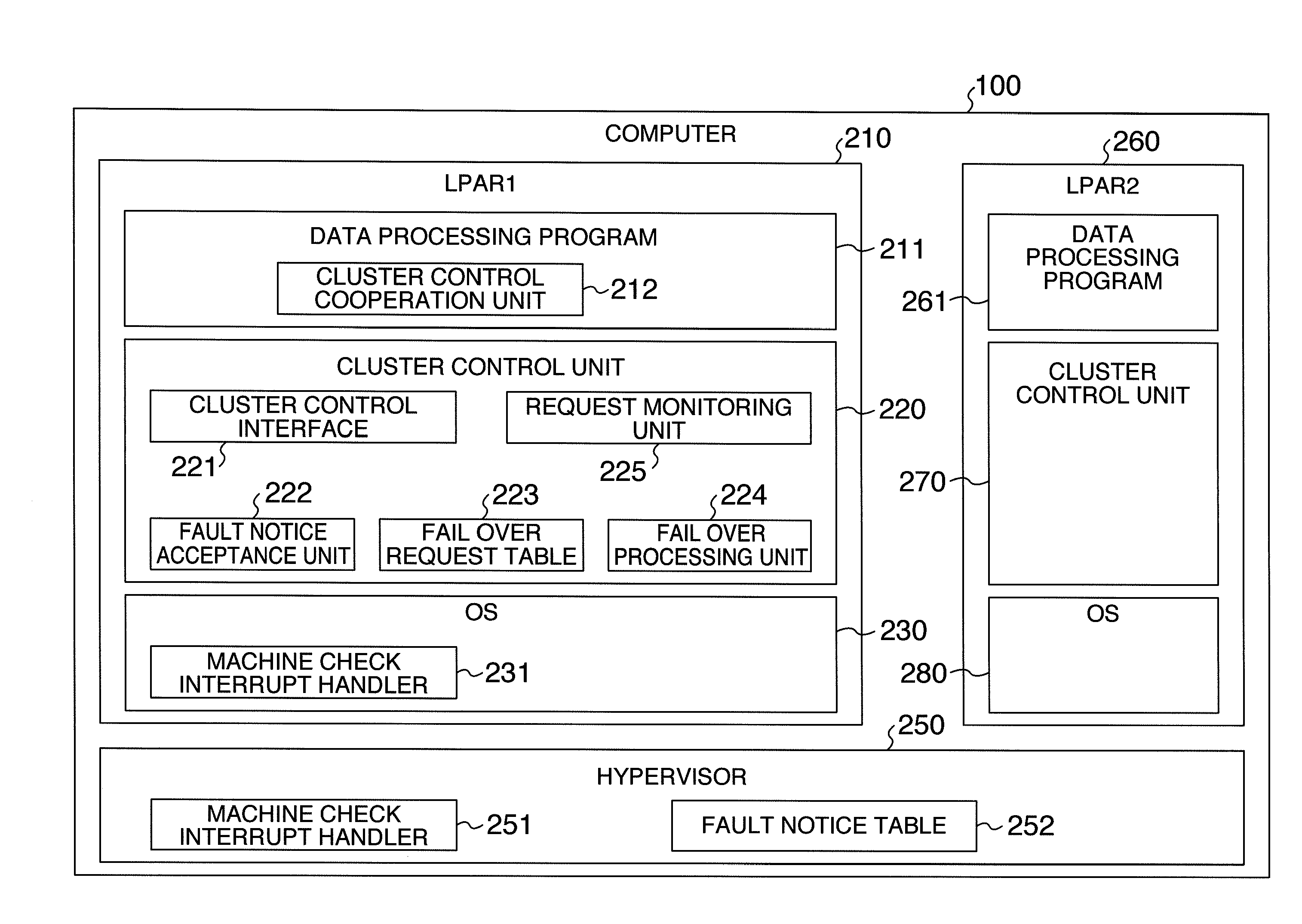
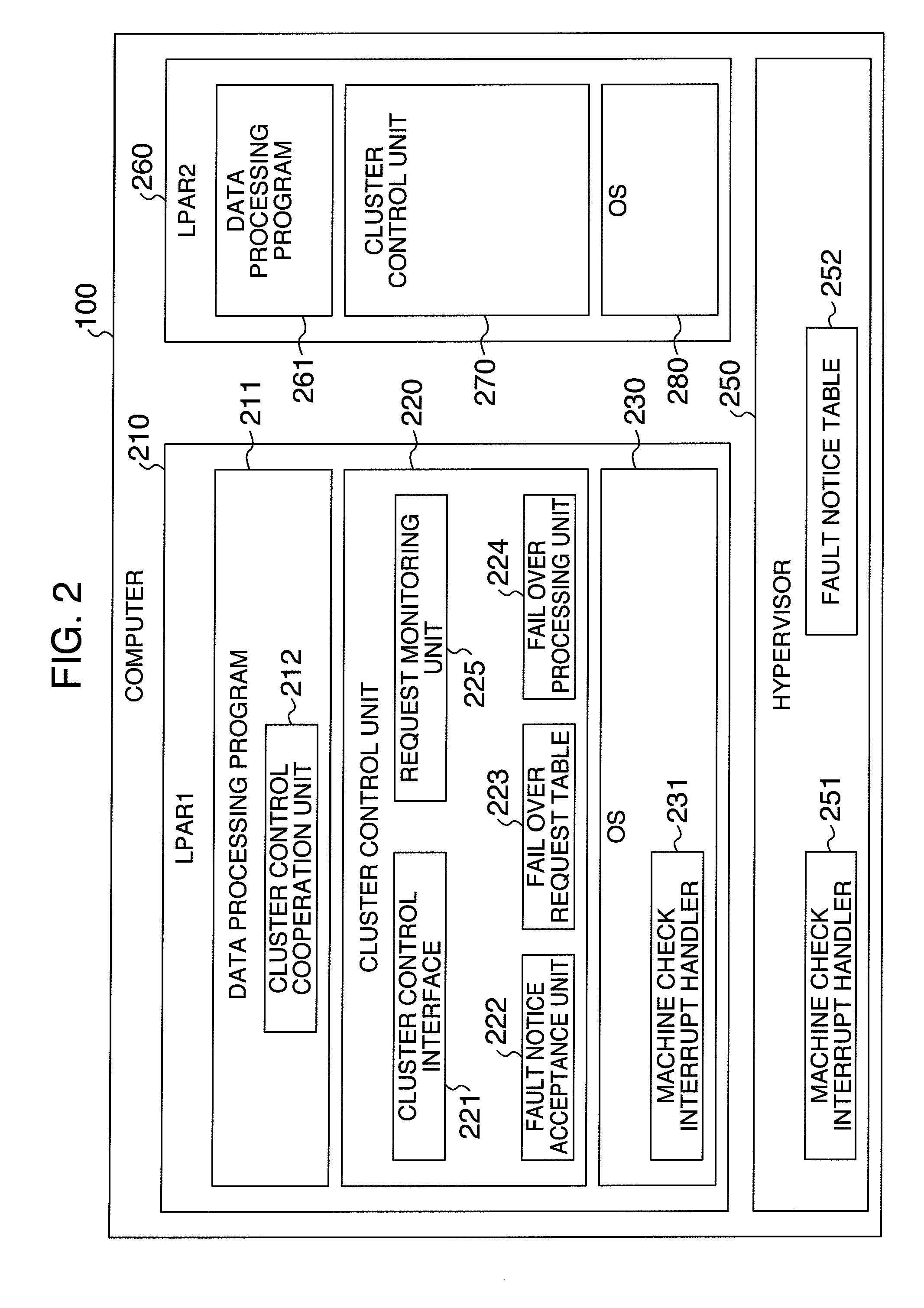
[0032]FIG. 3 is a diagram showing a configuration of a computer system according to embodiment 1 of the present invention. LPARs 210 and 310 executing in a computer 100 and a computer 200 constitute a cluster, and LPARs 260 and 360 executing in the computer 100 and the computer 200 constitute another cluster. It is supposed that the computer 100 is denoted by computer A and the computer 200 is denoted by computer B. It is supposed that in the computer 100 the LPAR 210 is LPAR1 in LPAR name and the LPAR 260 is LPAR2 in LPAR name. It is also supposed that in the computer 200 the LPAR 310 is LPAR3 in LPAR name and the LPAR 360 is LPAR4 in LPAR name. Furthermore, it is supposed that the LPAR 210 and the LPAR 260 constitute primary nodes in the clusters and the LPAR 310 and the LPAR 360 constitute backup nodes in the clusters.

[0033]In the computer 100, the LPARs 210 and 260 are...

embodiment 2

[0096]A second computer system according to the present invention will now be described. FIG. 9 is a system configuration diagram of an embodiment 2 according to the present invention.

[0097]In the embodiment 2, a computer 900 for monitoring the operation states of the computer 100 and the computer 200 is added to the system configuration in the embodiment 1. A NIC 931 and a NIC 932 are mounted respectively on the computer 100 and the computer 200, and are connected to the computer 900 via a network 920. It is made possible to refer to an interface of the hypervisor 250 via the network 920 and acquire contents of the fault notice table 252.

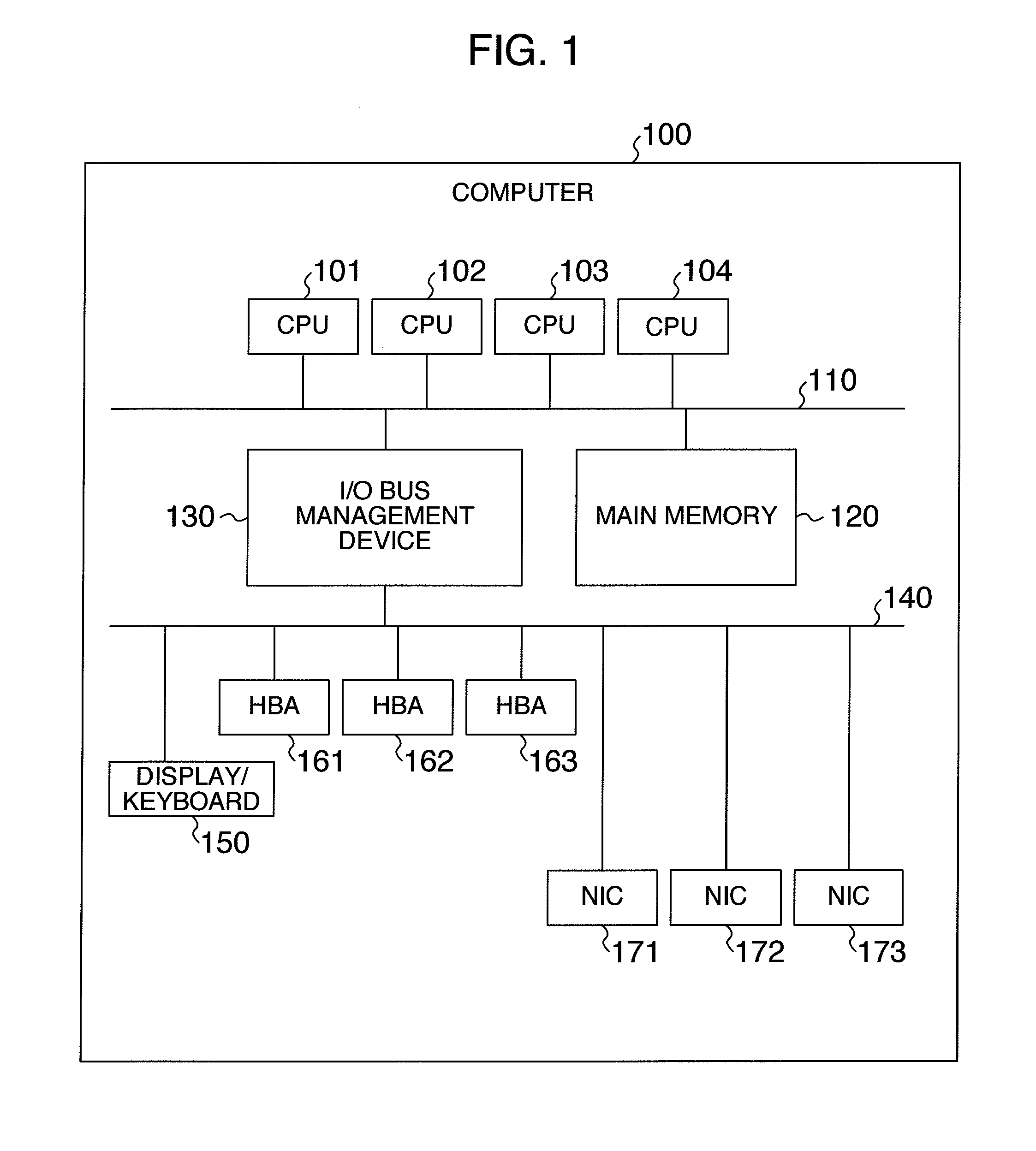
[0098]The computer 900 is a computer having a configuration similar to that shown in

[0099]FIG. 1. In the computer 900, a fault status display unit 910 is executing. The fault status display unit 910 acquires information from computers to be managed and displays the information. It is now supposed that the computer 100 and the computer 200 have been...


PUM


Abstract

As regards a hardware fault which has occurred in a computer, a hypervisor notifies an LPAR which can continue execution, of a fault occurrence as a hardware fault for which execution can be continued. Upon receiving the notice, the LPAR notifies the hypervisor that it has executed processing to cope with a fault. The hypervisor provides an interface for acquiring a situation of a notice situation. It is made possible to register and acquire a situation of coping with a hardware fault allowing continuation of execution through the interface, and it is made possible to make a decision as to the situation of coping with a fault in the computers as a whole.

Description

INCORPORATION BY REFERENCE[0001]The present application claims priority from Japanese application JP2011-096689 filed on Apr. 25, 2011, the content of which is hereby incorporated by reference into this application.BACKGROUND OF THE INVENTION[0002]The present invention relates to a processing method for a partial fault in a computer system in which a plurality of LPARs (Logical PARtitions) are executing owing to logical partitioning.[0003]As methods for utilizing a computer effectively, there are virtualization and logical partitioning. According to these techniques, virtual computers can be constituted on one physical computer and consequently the capability of the physical computer can be utilized effectively. As the computer performance is improved, it becomes possible in inexpensive computers as well to utilize the virtualization and logical partitioning and they are widely used.[0004]Each computer has various hardware fault detection mechanisms. The computer detects an abnormal...

Claims


Application Information

Patent Timeline
IPC IPC(8): G06F11/20
CPCG06F11/0712G06F11/2038G06F11/2028G06F11/0793
Inventor SEKIGUCHI, TOMOKIUENO, HITOSHI
Owner HITACHI LTD
Why Eureka
Try Eureka