
Ghost artifact reduction for rendering 2.5D graphics

a technology of ghost artifacts and rendering, applied in the field of image processing systems, can solve problems such as ghost artifacts, and achieve the effect of easy detection of occlusion

Active Publication Date: 2010-10-26
KONINK PHILIPS ELECTRONICS NV
View PDF5 Cites 16 Cited by
  • Summary
  • Abstract
  • Description
  • Claims
  • Application Information

AI Technical Summary

Benefits of technology

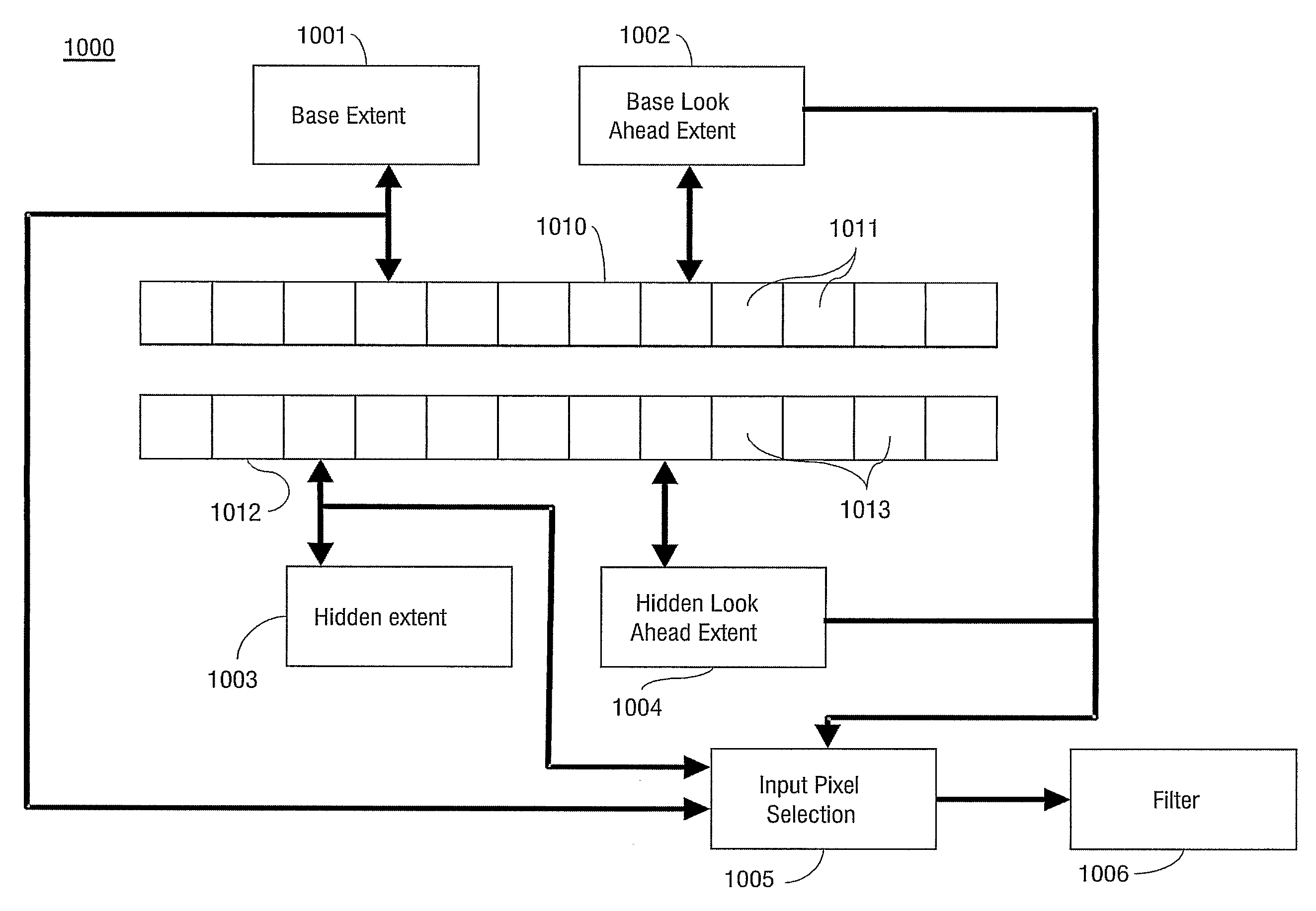
[0007]To meet the object of the invention, an image processing system as described in the first paragraph is provided comprising: an input for receiving the input image and a hidden image, a video processor being operative to create output pixels of the output image and an output for providing the output image for subsequent rendering. The input image is a pre-filtered 2D representation of 3D objects as seen from the input viewpoint and comprises for each input pixel an associated input pixel value and an associated input pixel depth. The hidden image is another 2D representation of the 3D objects and comprises information, which information is at least partly occluded from the input viewpoint. The video processor is operative to create the output pixels by transforming each input pixel to a transformed input pixel, associated with the output viewpoint, as a function of the input pixel depth and creating the output image based on the transformed input pixels, using hidden image pixels for filling de-occluded areas and for at least one pixel position adjacent to the de-occluded areas for preventing ghost line artifacts, caused by transformation of the pre-filtered input image.
[0009]De-occlusion may occur at depth discontinuities in the input image. Due to pre-filtering of the camera that records the original video, the pixels in the vicinity of the depth discontinuity contain color from both the foreground and the background objects in the input image. Therefore, simply filling the hole with de-occluded pixels from the hidden layer will result in a noticeable ghost line artifact. It is an advantage of the image processing system according to the invention that ghost line artifacts near the de-occluded hidden image pixels are prevented. This advantage is obtained by rendering a larger part of the hidden layer for replacing transformed input pixels adjacent to the de-occluded parts of the hidden layer. The hidden image pixels in the larger part of the hidden layer are inserted into the output image instead of the corresponding transformed input pixels.
[0010]In an embodiment of the invention the depth-dependent transformation is a transformation from the input viewpoint to a predetermined output viewpoint and the hidden image is associated with the output viewpoint. The predetermined distance may for example be a distance between a left and a right eye for providing a depth sensation. The input image may be obtained by a first camera in a position of a left eye viewpoint and the hidden image by a second camera in a position of a right eye viewpoint. Not all information recorded by the second camera has to be stored in the hidden image. Only information in and adjacent to the areas that are de-occluded with a transformation from the left eye input viewpoint to the right eye output viewpoint has to be stored in the hidden image. After transformation of the input image, this information is used to fill the de-occluded areas in the output image and to prevent ghost line artifacts near the de-occluded areas.
[0011]In another embodiment the hidden image is associated with the input viewpoint and the hidden image pixels are associated with a hidden image pixel value and a hidden image pixel depth, the video processor being operative to transform each hidden image pixel to a transformed hidden image pixel, associated with the output viewpoint, as a function of the hidden image pixel depth, and to create the output image using transformed hidden image pixels for filling de-occluded areas and for at least one pixel position adjacent to the de-occluded areas. This embodiment is particularly useful for providing the possibility to perform various transformations over various distances. The input image may be obtained from a first viewpoint by a first camera and the hidden image from a second viewpoint by a second camera. Preferably the information recorded by the second camera is then transformed to the first viewpoint. As a consequence the input image and the hidden image are thus associated with the same viewpoint. From this viewpoint both images may undergo the same transformation to an arbitrary output viewpoint.
[0013]Sequentially processing the pixels per row in a direction opposite a displacement from the input viewpoint to the output viewpoint makes it easy to detect occlusion. This can be done by maintaining an x-coordinate extent indicating a furthest x-coordinate of the pixels and their footprints that have been transformed so far. If the transformation of the next footprint results in increasing the extent the transformed next footprint is at least partly not occluded. In this way it can be decided easily whether or not to exclude a pixel from the output image. Preferably, the x-axis is horizontal and the camera displacement also. If so desired, other directions are possible as well. The video processor is operative to determine that a hidden image pixel is de-occluded if a transformed input pixel increases the x-coordinate extent by more than a predetermined threshold. Preferably, if the x-coordinate of the input pixel after transformation is more than 1.5 pixels away from the last pixel position in the output image, the hole is too big and is filled with at least one pixel from the hidden layer. Since it is desired to use pixels from the hidden layer for pixel positions before the de-occluded area, a means is needed to detect the de-occlusion before the transformed input pixels of the input image are enclosed in the output image. Backtracking is usually not possible because color values are accumulated in the video filter. For early detection of the de-occluded area, the video processing may include maintaining a look ahead extent.

Problems solved by technology

Therefore, simply filling the hole with de-occluded pixels from the hidden layer will result in a noticeable ghost line artifact.

Method used


Image

  • Ghost artifact reduction for rendering 2.5D graphics
  • Ghost artifact reduction for rendering 2.5D graphics
  • Ghost artifact reduction for rendering 2.5D graphics

Examples


Embodiment Construction

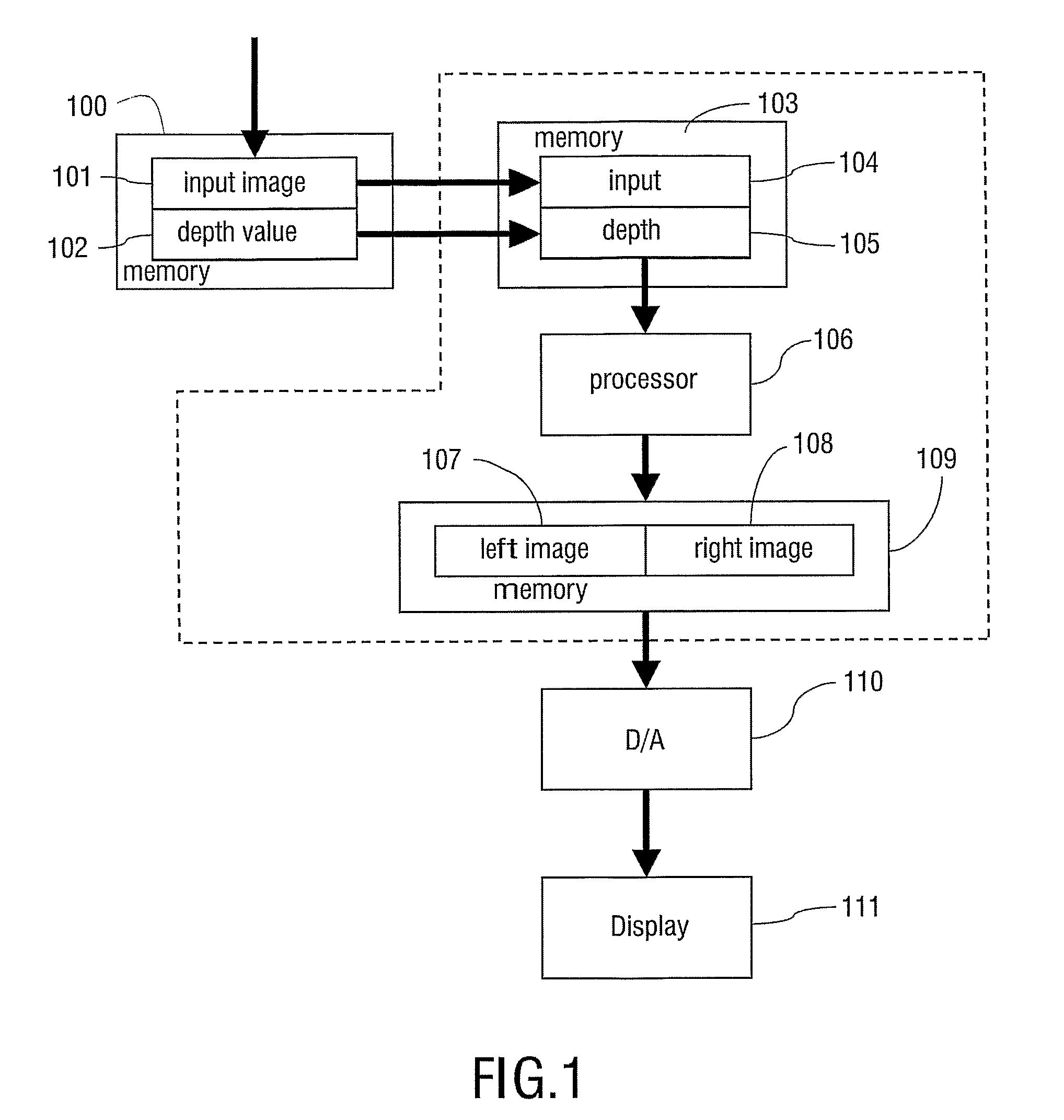
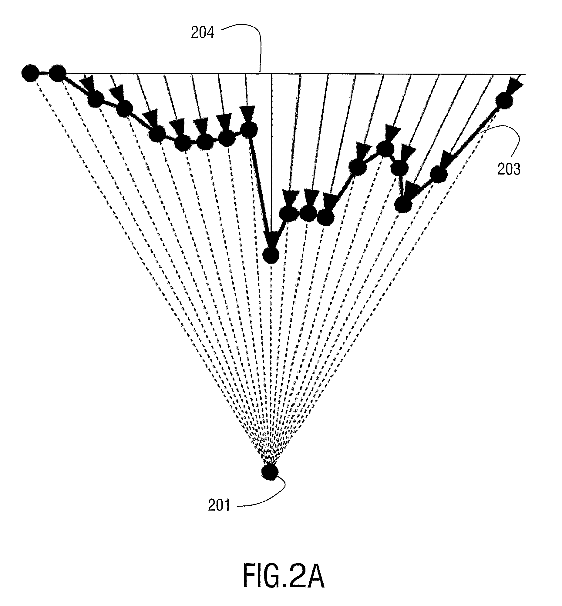
[0026]To explain the system according to the invention, with reference to FIGS. 1 to 5, depth dependent transformation will be described. In this general description a pixel is regarded as a point (dimensionless). FIG. 1 shows a block diagram of a conventional system in which the image processing system according to the invention may advantageously be used. The conventional system comprises a memory 100, such as a graphics memory, for storing a 2D input image 101. The input image 101 is comprised of an array of pixels divided in rows and columns. For each pixel a pixel value is given. Various ways of representing a pixel value are well known, such as an RGB (Red, Green, Blue) or YUV coding. The pixel value may be stored in full, e.g. using 16 or 24 bits per pixel. Alternatively, a Color Look-Up Table (CLUT) scheme may be used to code the pixel value using fewer bits, e.g. 8 bits. In addition to the pixel value, for each pixel a depth value is stored in the memory 100 as the input de...


PUM


Abstract

An image processing system for performing a transformation of an input image associated with an input viewpoint to an output image associated with an output viewpoint. The input image is a pre-filtered 2D representation of 3D objects as seen from the input viewpoint, and comprises for each input pixel an associated input pixel value and an associated input pixel depth. Additional to the input image a hidden image is received, being another 2D representation of the 3D objects and comprising information, which information is occluded from the input viewpoint.The system comprises a video processor being operative to create the output image by transforming each input pixel to a transformed input pixel. The transformation is a function of the input pixel depth. The output image is created, based on the transformed input pixels, using hidden image pixels for filling de-occluded areas and for at least one pixel position adjacent to the de-occluded areas. As a consequence ghost line artifacts, caused by transformation of the pre-filtered input image, are prevented.

Description

FIELD OF THE INVENTION[0001]This invention relates to an image processing system for generating at least one output image associated with an output viewpoint from an input image associated with an input viewpoint through a depth-dependent transformation, the images being represented as an input pixel array and an output pixel array, respectively.[0002]This invention further relates to a method and a computer program product.BACKGROUND OF THE INVENTION[0003]The interest in providing a depth sensation when displaying an image on a 2D display is growing rapidly, notably in virtual reality applications and computer games. Various forms of providing depth cues, such as influencing the brightness level or the size of an object, are known. Particularly, stereopsis, or stereoscopic vision, receives much attention as a technique for providing depth sensation. Stereopsis is evoked by presenting to a person two 2D images of the same scene as observed from two positions a little way apart. One ...

Claims


Application Information

Patent Timeline
Patent Type & Authority Patents(United States)
IPC IPC(8): G06K9/00G06T15/20
CPCG06T15/20
Inventor BERRETTY, ROBERT-PAUL MARIO
Owner KONINK PHILIPS ELECTRONICS NV
Learn More