Emphasizing image portions in an image

a technology of image portions and image enhancement, applied in image enhancement, television systems, instruments, etc., can solve the problems of increasing risk, increasing risk, and difficult to achieve the effect of maximum sharpness

Inactive Publication Date: 2008-04-10
NOKIA CORP
View PDF5 Cites 16 Cited by
  • Summary
  • Abstract
  • Description
  • Claims
  • Application Information

AI Technical Summary

Benefits of technology

[0005]One possibility to indicate the area of sharp focus is to display a rectangle, which has a fixed size and is centered around a single image area for which a maximum sharpness has been determined. Such a rectangle, due to its fixed dimensions, also may frame blurred areas that are situated close to the area of maximum sharpness, for instance in macro photography. Such a rectangle, which only indicates the area of maximum sharpness, does furthermore not provide the user with an idea of the actual area of adequate sharpness throughout the entire image. As a result, peripheral areas of a target that is preferred by a user to be in focus easily end up blurry by accident.

Problems solved by technology

Generally, when using a digital camera with autofocus and zoom optics, there is a high risk of unwanted blurring of the important image areas, i.e. the depth of field may be too small (or too large), or simply, the camera may be focused to the wrong area of the image field.
Especially, when shooting objects in close distance, i.e. when the focus is not in infinity, this risk increases.
This may become quite difficult, since the camera display—for instance when being integrated into a mobile phone—may be too small to adequately determine whether the image is correctly focused or not.
The result often is that an image, which is assumed to be in good focus, later turns out to be partly or totally blurred, when viewed on a larger display, such as for instance a computer screen.
Such a rectangle, which only indicates the area of maximum sharpness, does furthermore not provide the user with an idea of the actual area of adequate sharpness throughout the entire image.
As a result, peripheral areas of a target that is preferred by a user to be in focus easily end up blurry by accident.

Method used


Image

  • Emphasizing image portions in an image
  • Emphasizing image portions in an image
  • Emphasizing image portions in an image

Examples


Embodiment Construction

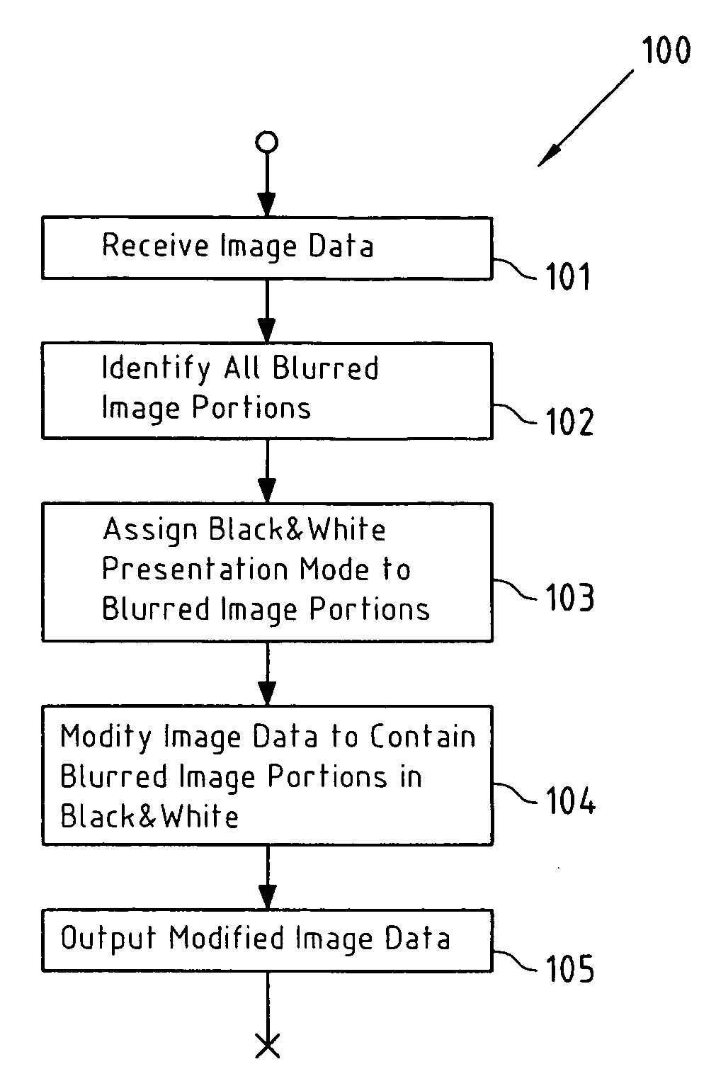
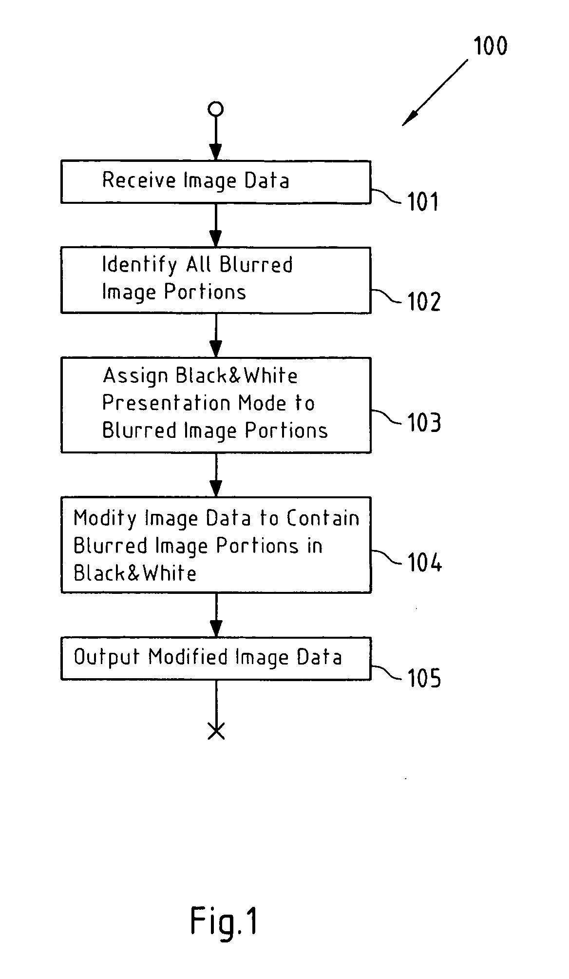
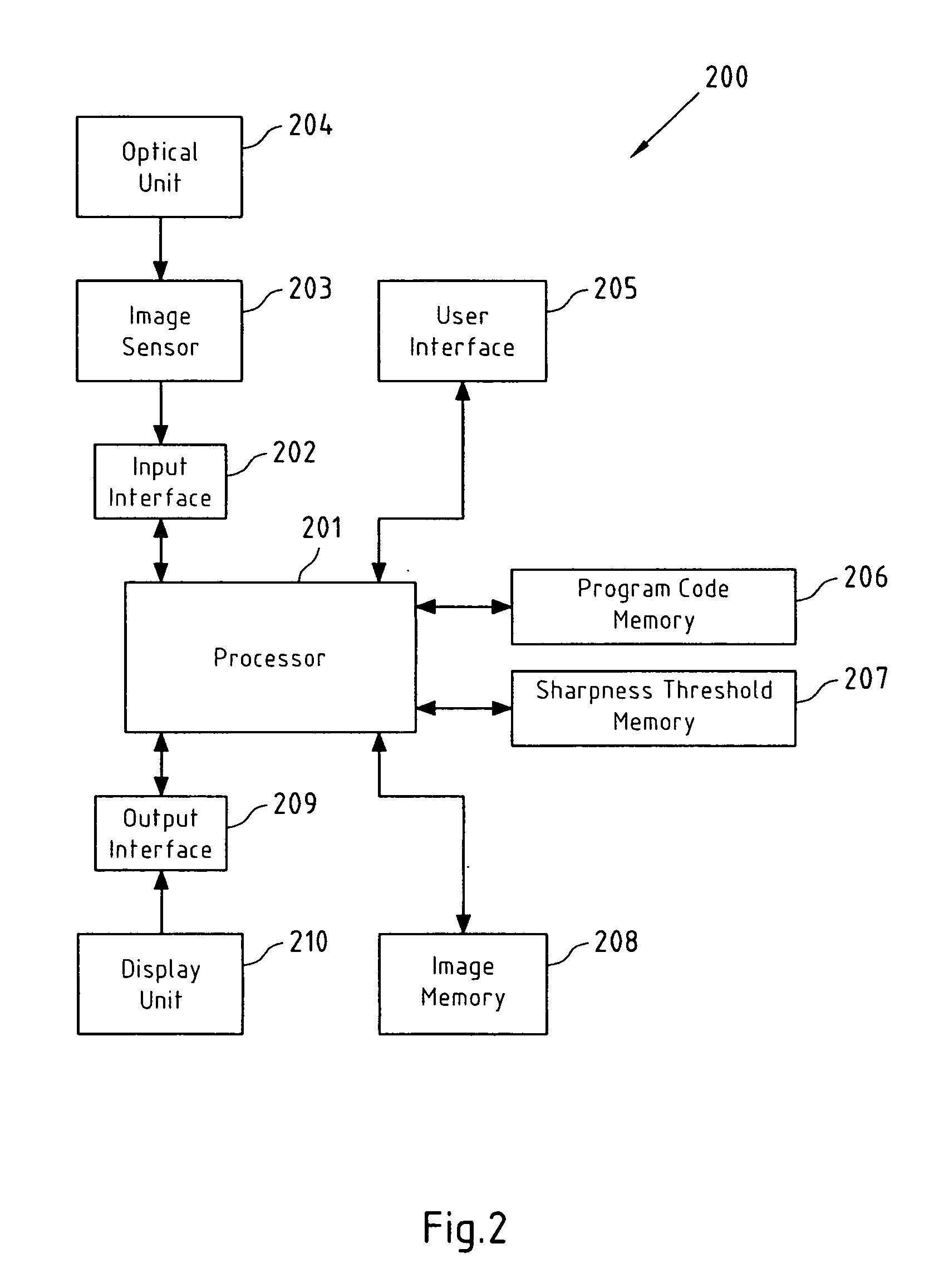
[0050]FIG. 1 depicts a flowchart 100 of an exemplary embodiment of a method for emphasizing specific image portions in an image according to the present invention. The steps 101 to 105 of flowchart 100 may for instance be performed by processor 201 (see FIG. 2) or processor 304 (see FIG. 3). In this exemplary example, it is assumed that all blurred image portions in the image are considered as the specific image portions.

[0051]In a first step 101, image data is received, wherein said image data represents an image. In a second step 102, all blurred image portions in said image are identified. Alternatively, also all sharp image portions in said image, or both sharp and blurred image portions could be identified. Said identifying may for instance be performed as described with reference to flowchart 400 in FIG. 4 below. In a step 103, a black-and-white presentation mode is assigned to the identified blurred image portions. In a step 104, the image data is then modified to contain sai...


PUM


Abstract

This invention relates to a method, a computer readable medium and apparatuses in the context of emphasizing image portions in an image. Image data representing an image is received, the image data is processed to identify specific image portions in the image, wherein the specific image portions are one of a plurality of sharp image portions and a plurality of blurred image portions; and a specific presentation mode is assigned to the specific image portions in the image.

Description

FIELD OF THE INVENTION[0001]This invention relates to a method, apparatuses and a computer-readable medium in the context of emphasizing specific image portions in an image.BACKGROUND OF THE INVENTION[0002]Emphasizing specific image portions in an image is for instance desirable in the application field of digital photography, where said specific image portions may for instance be sharp image portions or blurred image portions.[0003]Generally, when using a digital camera with autofocus and zoom optics, there is a high risk of unwanted blurring of the important image areas, i.e. the depth of field may be too small (or too large), or simply, the camera may be focused to the wrong area of the image field. Especially, when shooting objects in close distance, i.e. when the focus is not in infinity, this risk increases. Macro photography is an extreme example of this—when the object distance is only a few dozens centimeters, the depth of field is often only a few centimeters.[0004]When ta...

Claims


Application Information

Patent Timeline
Patent Type & Authority Applications(United States)
IPC IPC(8): G06K15/02
CPCH04N5/23212H04N5/23293H04N5/23222H04N23/64H04N23/80
Inventor KAUHANEN, PETTERI
Owner NOKIA CORP
Why Eureka
Try Eureka