Improved objective phoropter

Active Publication Date: 2018-05-03
VISIONIX
View PDF0 Cites 1 Cited by
  • Summary
  • Abstract
  • Description
  • Claims
  • Application Information

AI Technical Summary

Benefits of technology

The present disclosure describes new systems for performing objective phoropter measurements. These systems use a keratometric measurement system to accurately position the subject's eyes for the measurement. One improvement is the calibration of the lens wheel combinations used to correct the subject's vision during the phoropter measurement. The entire phoropter wheel, covering the entire measurement range, can be accurately calibrated to ensure more accurate prescribed correction lenses for the subject. Additionally, the control unit can perform the focusing of the lens wheel of the instrument relative to the cornea of the eye and determines when the images of the reflection from the cornea of the eye have maximum sharpness. Overall, these systems provide more accurate and convenient results for objective phoropter measurements.

Problems solved by technology

In the first place, the accuracy of the systems rely on the nominal values of the lenses used in the lens wheels, such that if any of the lenses have an inaccurate value, the supposed optical power of the lens combination used will be incorrect, and the prescription output for preparing correction spectacle lenses will be inaccurate.
Such inaccuracy can also arise because of poor alignment of the lens wheels.
As a result, the vision correction prescription will not provide the optimum correction possible for the subject.
Additionally, the subject's eyes may not be positioned at the correct distance from the phoropter lens wheels, and since this distance is important for prescribing lenses which will provide optimum correction in a spectacle frame which is designed to sit at a standard distance from the user's eyes, any deviation therefrom will result in less than optimum vision correction.
The same consideration applies to the lateral centering of the subject's eyes during the measurements, and prior art methods using the pupil image to center the eye during the measurements may not be optimal.

Method used


Image

  • Improved objective phoropter
  • Improved objective phoropter
  • Improved objective phoropter

Examples


Embodiment Construction

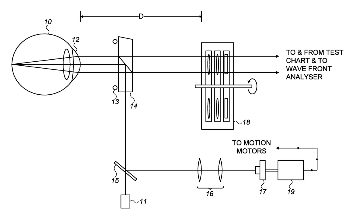
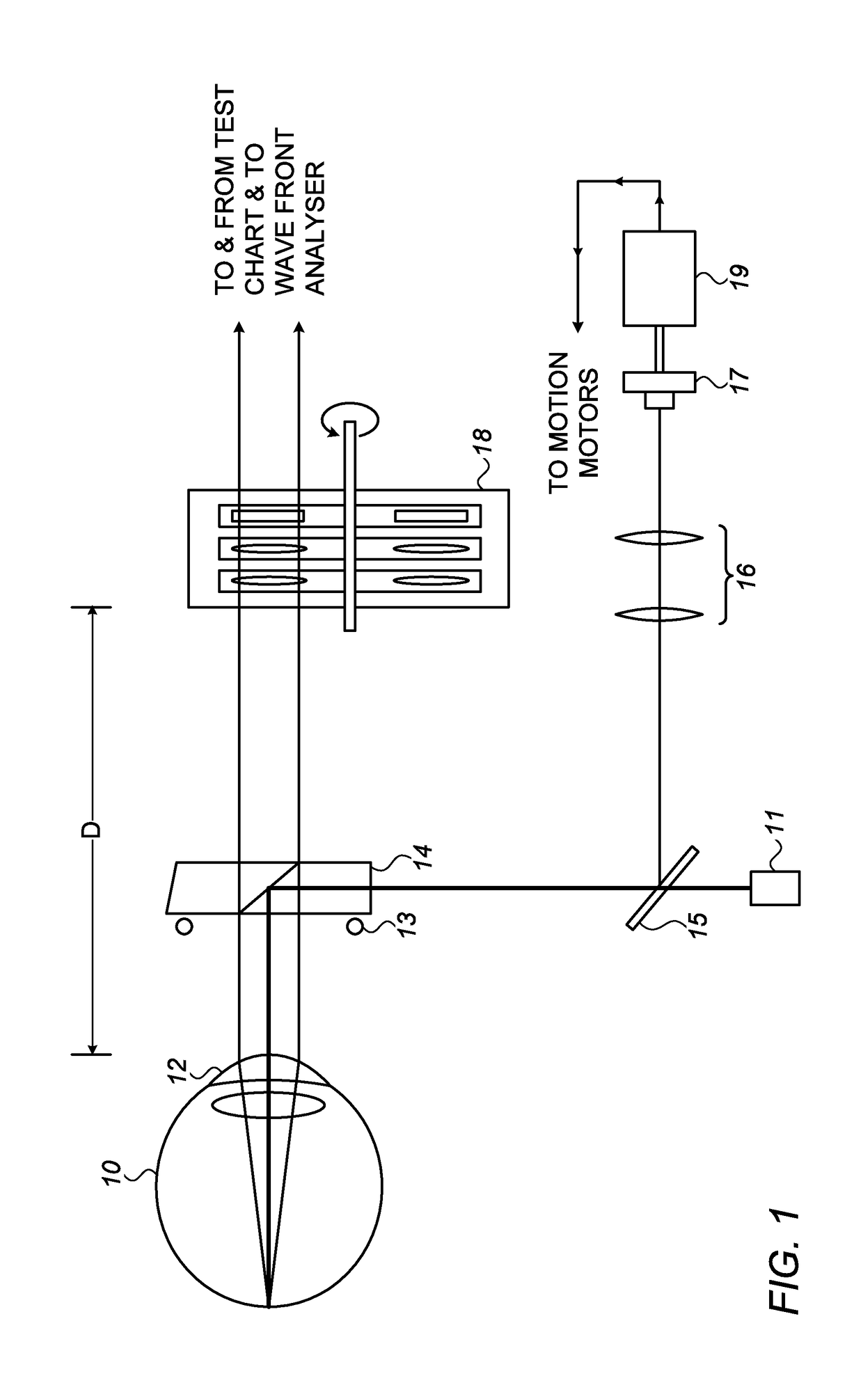
[0034]Accurate lateral centering and longitudinal focussing of the eye are important operations necessary for ensuring good accuracy for many ophthalmic measurements. The correct position of focus is important, not only for the phoropter measurement but also for the wavefront measurement of the present instrument. A pair of spectacles should be worn at a predetermined distant from the eye, in order that the prescription accurately compensates for the eye's aberrations. The correct distance is important because the image is effectively focused onto the subject's retina by a combination of the lens of the subject's eye and the spectacle lens in front of that eye. The longitudinal distance between those two lenses is one of the parameters that determines the power of such a combination of spaced lenses. It is for this reason that a standard distance D of the spectacle lenses from the front surface of the eye is assumed in ophthalmic prescriptions, and this convention is used for determ...


PUM


Abstract

An objective phoropter utilizing an illuminated keratometric object projecting its illumination onto the subject's cornea, and imaging the reflection therefrom in an imaging camera. Image processing of these images is used to improve the focusing and centering of the cornea subject's eyes. Once the correctly focused position of the eyes is obtained relative to the keratometer object, an accurate longitudinal position of the eyes relative to the lens wheel assemblies can also be achieved. This results in more accurate prescription generation than in prior art systems where the eyes may not be accurately positioned relative to the lens wheels. Additionally, the lens combinations of the entire phoropter wheel can be calibrated using an artificial eye having adjustable levels of aberration. Each lens combination is adjusted to supposedly correct a selected aberration level, and any residual aberration measured represents the correction to be applied to that lens combination.

Description

FIELD OF THE INVENTION[0001]The present invention relates to the field of objective phoropter measurements, using instruments incorporating iterative subjective phoropter measurements with objective wavefront analysis measurements, especially involving calibration methods for the lens wheels of the phoropter, and for increasing the accuracy of the centering and focusing, and of the longitudinal position of the eyes of the subject in the instrument during the measurements.BACKGROUND OF THE INVENTION[0002]There exist systems for performing combined phoropter and refractive measurements to ascertain the aberrations present in the eye of a subject. One such system is described in International Patent Publication No. WO / 2013 / 150513, for “Objective Phoropter System” having common inventors with the present application, and co-assigned with the present application. That system uses a pair of phoropter wheel assemblies, one for each eye, each assembly comprising a number of lens wheels inco...

Claims


Application Information

Patent Timeline
IPC IPC(8): A61B3/10A61B3/117A61B3/14
CPCA61B3/1015A61B3/117A61B3/14A61B2560/0238A61B3/0285A61B3/107A61B3/18A61B3/145
Inventor ABITBOL, MARCYAM, RANHERMAN, HAGGAIMELNICK, IANSOMPOLINSKY, ADERET
Owner VISIONIX
Why Eureka
Try Eureka