Localization of a point source of a visualized gas leak

a gas leak and point source technology, applied in the field of localization of a visualized gas leak, can solve the problem that the origin of the leak can typically take weeks or months, and achieve the effect of improving the localization of the point sour

Active Publication Date: 2005-03-03
GAS OPTICS AS
View PDF3 Cites 16 Cited by
  • Summary
  • Abstract
  • Description
  • Claims
  • Application Information

AI Technical Summary

Benefits of technology

An object of the present invention is thus to improve the localization of a point source of a visualized gas leak. An aim of the object is to provide au

Problems solved by technology

Locating the origins of these leaks can typica

Method used


Image

  • Localization of a point source of a visualized gas leak
  • Localization of a point source of a visualized gas leak
  • Localization of a point source of a visualized gas leak

Examples


Embodiment Construction

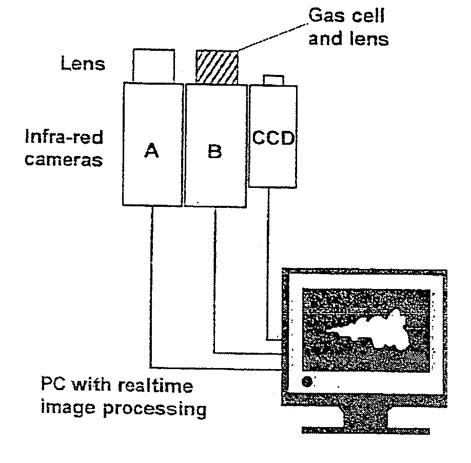
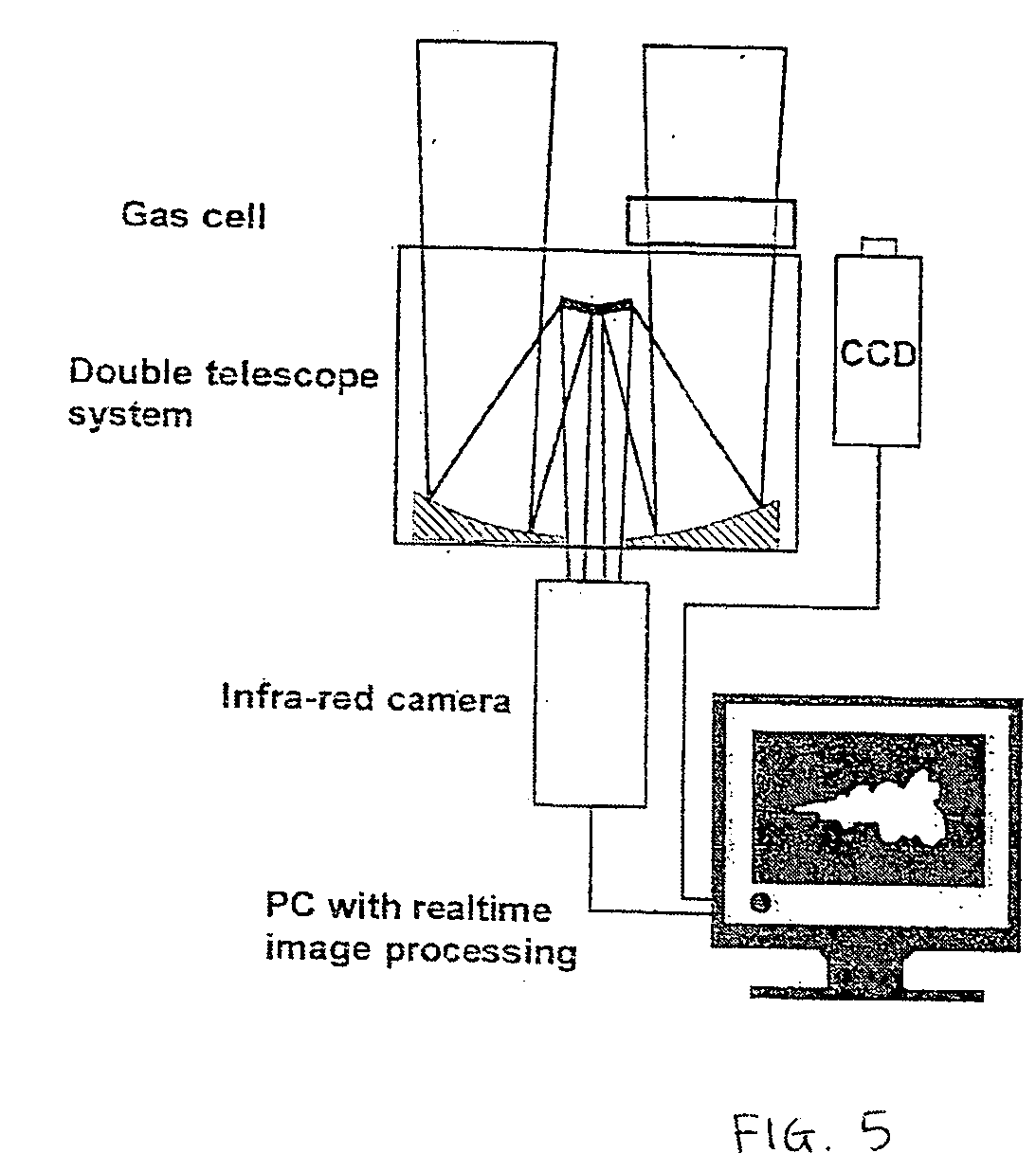
The invention thus refers to localization of one or several point sources of a visualized gas leak. Especially the present invention refers to automatic localization of one or several point sources of a visualized gas leak using for instance the gas correlation technique.

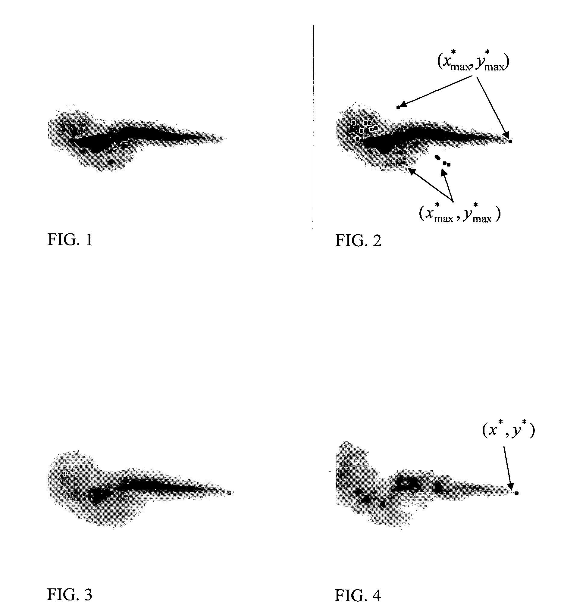
The present invention relies on a number of physical properties of gas leaks. The most important ones are the turbulent structure of the gas at different distances from the gas source and the fixed location in space of the gas source. The occurrence of a strong concentration gradient which features a corner-shaped behavior in the gas images at the source is also used.

The gas concentration distribution is a four-dimensional function in time and space. Gas visualization techniques project this function to a three-dimensional function by integrating along one of the space coordinates, or more precisely, integrating along the lines corresponding to the same point in the projective transform. In this description tex...


PUM


Abstract

Automated localization of a point source of a visualized gas leak, by searching in a corner response function crf(x*,y*,τ), calculated based on a number of frames of said gas leak, for maximum values in the (x*,y*) variables that are stable over the time variable τ. Considering a point (x*,y*) as said point source if said corner response function crf(x*,y*,τ) has a maximum value in said point (x*,y*) and said point (x*,y*) is temporally stable.

Description

FIELD OF THE INVENTION The present invention refers to localization of a point source of a visualized gas leak. Especially the present invention refers to automatic localization of a point source of a visualized gas leak using for instance gas correlation technique. BACKGROUND OF THE INVENTION When using visualization systems to monitor leaks in a gas processing plant, there is a need to quickly and automatically locate the origin of the leak in the gas processing plant in order to take appropriate counter-actions. If the leak is a security risk it is favorable to shut down the production automatically without human intervention. If the location of the point source of the leak is not known then the entire plant has to be shut down to control the leak. Clearly, it is of economical interest to only shut down the affected subsystems. If a shutdown decision should be taken by an operator it is useful to translate the optical information in the gas image to schematic information in an...

Claims


Application Information

Patent Timeline
IPC IPC(8): G01M3/38G01N21/35
CPCG01N21/3518G01M3/38
Inventor ARDO, BJORN BENJAMINCHRISTIANSSON, TOMAS KRISTLANSANDSTEN, JONAS PER
Owner GAS OPTICS AS
Why Eureka
Try Eureka