
Printer

a printing machine and paper cutting technology, applied in printing, metal working equipment, other printing equipment, etc., can solve the problem of reducing the force of the press member to press the cut-off paper stacked in the paper stacking portion, and achieve the effect of reducing the maximum load

Active Publication Date: 2012-11-01
STAR MICRONICS
View PDF12 Cites 9 Cited by
  • Summary
  • Abstract
  • Description
  • Claims
  • Application Information

AI Technical Summary

Benefits of technology

[0005]In order to solve the problem, an object of the present invention is to provide a printer capable of pushing a cut-off paper toward a paper stacking portion without an additional power source while reducing the maximum load applied to driving means for driving a movable blade.
[0023]According to the printer of the present invention, the cut-off papers can be pushed toward the paper stacking portion without an additional power source while reducing the maximum load applied to the driving means that moves the movable blade.

Problems solved by technology

On the contrary, when the angle of the press member contacting the n-th stacked cut-off paper is excessively small, the force of the press member to press the cut-off papers stacked in the paper stacking portion decreases.

Method used


Image

  • Printer
  • Printer
  • Printer

Examples


Embodiment Construction

[0034]Hereinafter, embodiments of the present invention will be described with reference to the accompanying drawings.

[0035]A printer as an embodiment of the present invention may be a thermal printer adapted to draw out paper from a paper roll which is made by rolling an elongated heat sensitive paper and the like in a roll shape, perform printing on the paper, and cut a printed part of the paper.

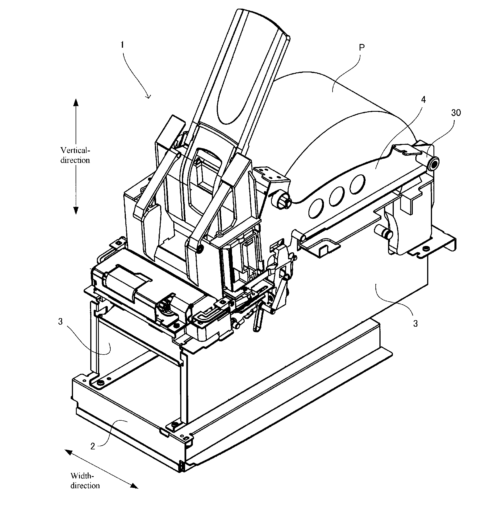
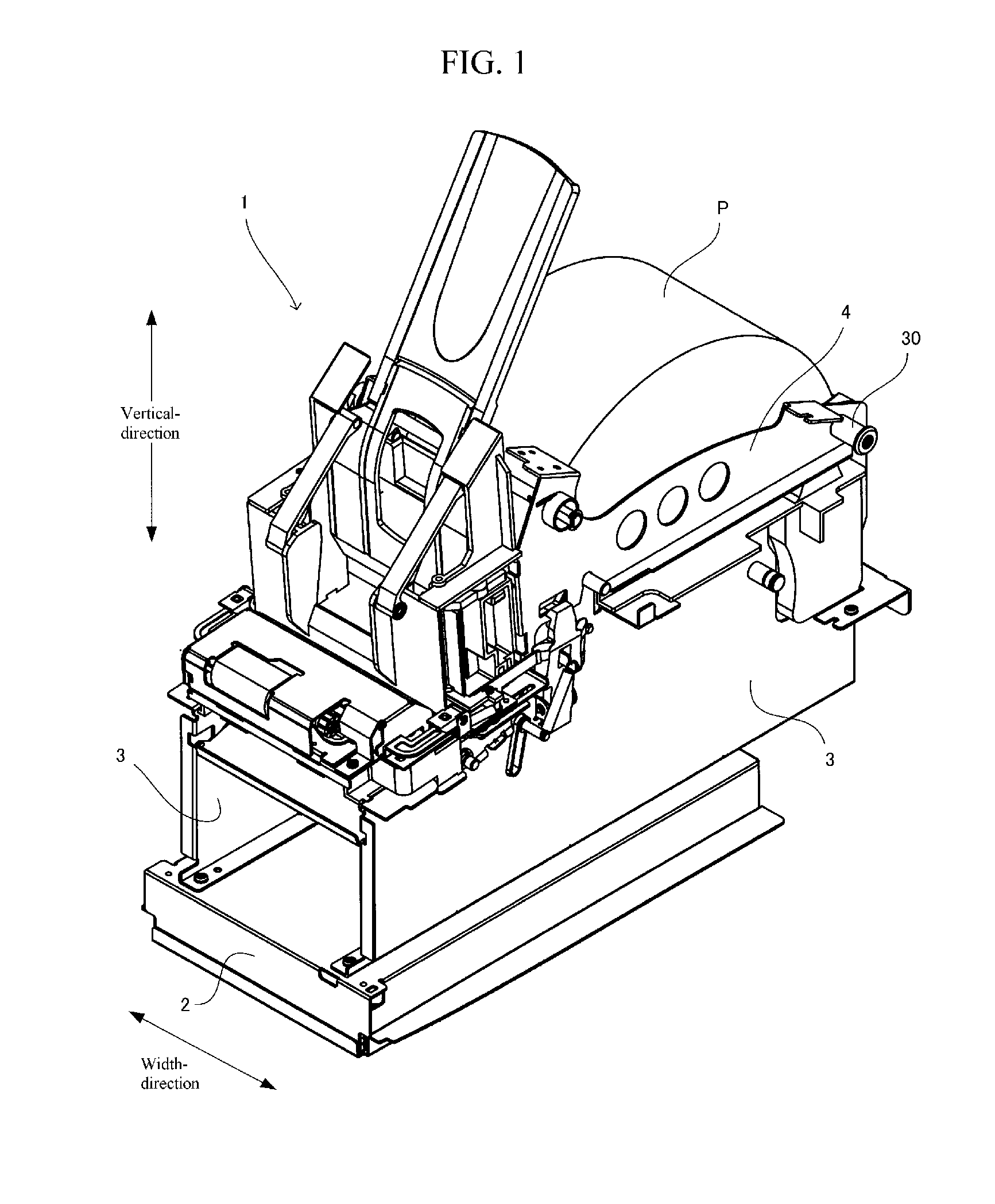
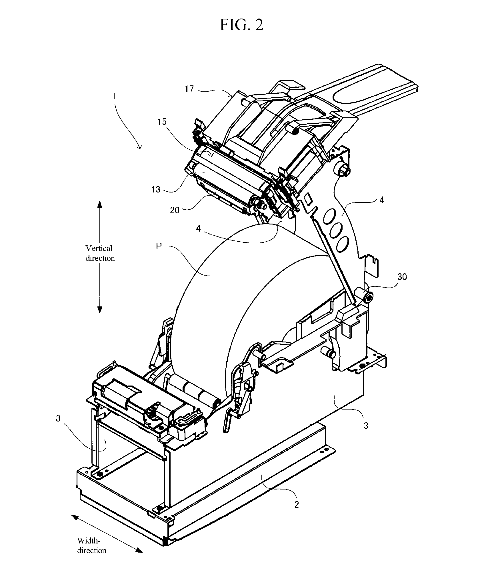
[0036]FIG. 1 is a front perspective view of a printer 1 according to an embodiment of the present invention, which is viewed from a diagonally upper right. Herein, a horizontal direction of the printer 1 (a direction perpendicular to a paper plane in FIG. 3) may be called a width direction.

[0037]As shown in FIG. 1, the printer 1 includes a base chassis 2 having a power supply or a control board embedded therein, a pair of left and right body frames 3 fixed to the base chassis 2, and a pair of left and right cover frames 4 rotatably coupled to the body frames 3. The cover frames 4 are rotat...


PUM

PropertyMeasurementUnit
angleaaaaaaaaaa
angleaaaaaaaaaa
thicknessaaaaaaaaaa

Abstract

Provided is a printer in which a cut-off paper is pushed into a paper stacking portion without an additional power source while reducing the maximum load applied to driving means for driving a movable blade. A printer includes a movable blade for cutting a paper disposed between a fixed blade and a movable blade as it moves in a forward direction and separating a printed part as a cut-off paper; driving means for moving the movable blade in a reciprocating manner; a pushing member which is driven to push a cut-off paper in a thickness direction of the cut-off paper; a paper stacking portion for stacking the cut-off paper pushed by the pushing member; and a driving force transferring mechanism for transferring a driving force of the driving means to the pushing member to drive the pushing member.

Description

CROSS-REFERENCE TO RELATED APPLICATION[0001]The present application claims priority to Japanese Patent Application No. 2011-101201 filed on Apr. 28, 2011, which is incorporated herein by reference as if reproduced in its entirety.BACKGROUND OF THE INVENTION[0002]The present invention relates to a printer including a movable blade for cutting paper disposed between a fixed blade and the movable blade, and a paper stacking portion for stacking cut-off papers thereon.[0003]Conventionally, there has been a printer comprising a movable blade for cutting paper disposed between a fixed blade and the movable blade as it moves in a forward direction, driving means for driving the movable blade back and forth, and a paper stacking portion for stacking a plurality of pieces of paper cut by the movable blade thereon. Japanese Patent No. 4,192,083 discloses a printer configured to push paper toward the paper stacking portion by means of a front end portion of the movable blade as it moves in the...

Claims


Application Information

Patent Timeline
Patent Type & Authority Applications(United States)
IPC IPC(8): B26D7/08
CPCB26D1/065B26D7/1818B41J15/042B41J13/106B41J11/70Y10T83/2074Y10T83/2098Y10T83/8691
Inventor KONDO, TOMOYUKIOGAWA, TAKESHI
Owner STAR MICRONICS
Learn More