Method for driving actuators

a technology of actuators and actuators, applied in the direction of electrical control, non-mechanical valves, magnetic bodies, etc., can solve the problems of large physical volume and high price of these electrical components, disadvantages, and considerable cost saving, and achieve the effect of reducing the maximum load and cost saving

Inactive Publication Date: 2008-02-12
ROBERT BOSCH GMBH
View PDF1 Cites 2 Cited by
  • Summary
  • Abstract
  • Description
  • Claims
  • Application Information

AI Technical Summary

Benefits of technology

[0003]The present invention proceeds from the recognition that, especially for applications in automotive engineering, absolutely simultaneous driving of all the actuators that are to be driven is not necessarily required. In the case of multi-channel output devices for pulsed driving of a plurality of actuators, it may instead be entirely tolerable for small time shifts to occur between the pulses. This allows the avoidance of so-called “rising edge collisions,” understood as the simultaneous occurrence of activation edges on multiple channels. Advantageously, the maximum load can thereby be reduced, because the current intensity occurring is lower than in the case of simultaneous driving of all actuators. This eliminates the need for overdimensioning of an output stage or of a power supply device that is supplying the required current, for example a DC / DC converter or capacitors, and thus results in a considerable cost saving.

Problems solved by technology

The problem occurring here is that depending on the current load required, only very expensive and high-quality components can be used.
The large physical volume and high price of these electrical components is, however, disadvantageous.
This eliminates the need for overdimensioning of an output stage or of a power supply device that is supplying the required current, for example a DC / DC converter or capacitors, and thus results in a considerable cost saving.

Method used


Image

  • Method for driving actuators
  • Method for driving actuators
  • Method for driving actuators

Examples


Embodiment Construction

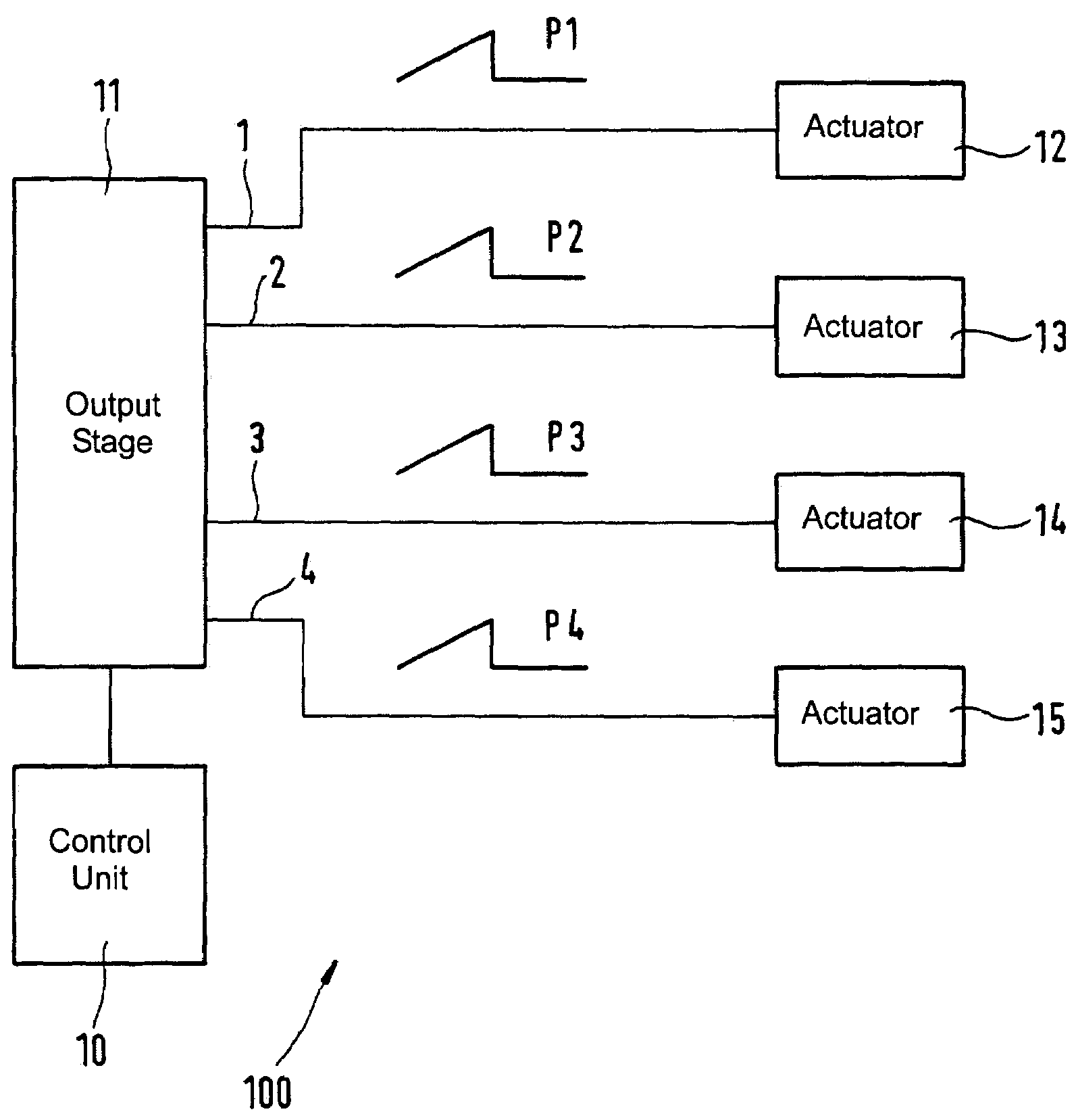
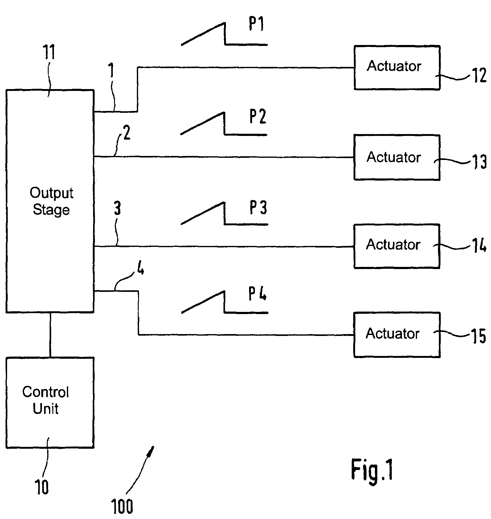
[0012]FIG. 1 is a first block diagram schematically depicting an electronic device 100 for driving actuators. Device 100 encompasses a control unit 10 that is connected to a multi-channel output stage 11. Multiple channels, for example channels 1, 2, 3, 4, of output stage 11 are connected to a plurality of actuators 12, 13, 14, 15. These actuators can be, for example, electromagnetic injection valves for controlling fuel delivery in a motor vehicle, or solenoid valves in connection with braking or steering devices of a motor vehicle, or a control system for the gas exchange valves of an internal combustion engine. Actuators 12, 13, 14, 15 are driven by pulses P1, P2, P3, P4 that are supplied by output stage 11.

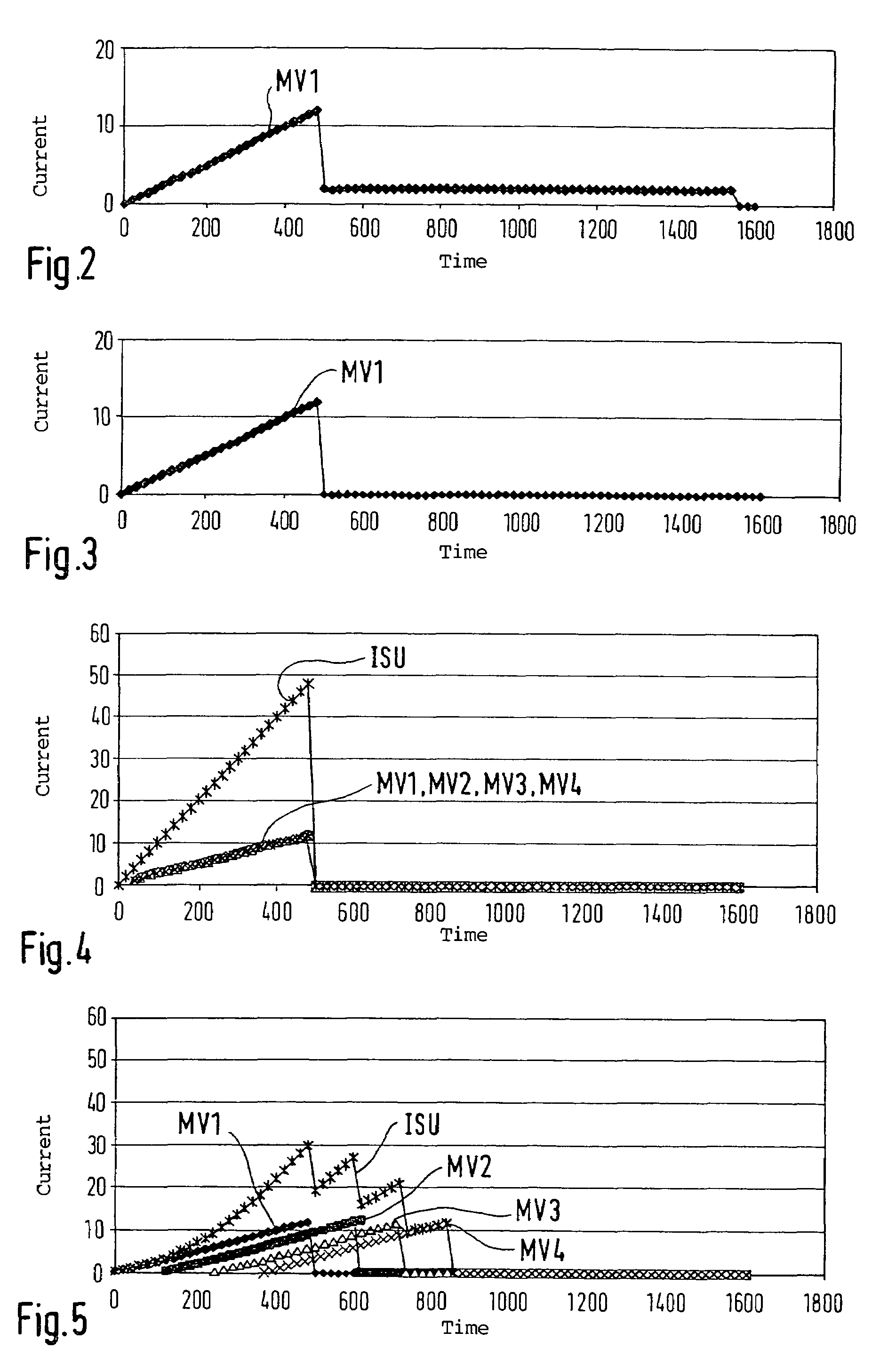
[0013]FIG. 2 is a first diagram depicting a current profile MV1 as a function of time. This is a typical current profile that occurs when an actuator, for example a solenoid valve, is driven. Time units, for example milliseconds, are plotted on the X axis. Current units, for e...


PUM

PropertyMeasurementUnit
timeaaaaaaaaaa
timeaaaaaaaaaa
boost currentsaaaaaaaaaa

Abstract

A method for driving a plurality of actuators having an output stage having multiple channels, by way of whose channels boost currents are conveyed to the actuators. In this method, a check is made as to whether rising edges of multiple boost currents are present simultaneously (rising edge collision). Upon the identification of simultaneously present rising edges, at least one of the boost currents is conveyed in time-offset fashion to the associated actuator.

Description

FIELD OF THE INVENTION[0001]The present invention relates to a method for driving actuators.BACKGROUND INFORMATION[0002]“Actuators” are to be understood, for purposes of this application, as electrical components or even assemblies that are driven by current pulses or voltage pulses. Solenoid valves, or actuators of an electrohydraulic valve control (EHVC) system, may be mentioned merely by way of example. The task often arises of driving a plurality of such actuators substantially simultaneously. Systems for multi-channel pulse generation to drive multiple actuators or their output stages, for example for ignition and fuel injection in motor vehicles, are already known in a variety of embodiments. In so-called boost output stages, the delivery of high power levels is required, albeit often only briefly. In this context, a rapid but only brief current superelevation typically ensures rapid and reliable energization of solenoid valves while simultaneously minimizing the electrical po...

Claims


Application Information

Patent Timeline
Patent Type & Authority Patents(United States)
IPC IPC(8): H02H9/00H01H51/22H01H51/30H01H47/00H01H47/14H01H47/32F01L9/20H01F7/18
CPCF01L9/04F02D41/20F01L2009/048F01L2800/00F02D2041/2082H01F7/1844H01F7/1877F01L2009/408F01L9/20
Inventor GAESSLER, HERMANNSCHIEMANN, JUERGEN
Owner ROBERT BOSCH GMBH
Why Eureka
Try Eureka