Landing gear

Active Publication Date: 2018-12-06
AIRBUS OPERATIONS LTD
View PDF0 Cites 1 Cited by
  • Summary
  • Abstract
  • Description
  • Claims
  • Application Information

AI Technical Summary

Benefits of technology

The patent describes using two arms connected to a shock absorber to integrate the landing gear into an aircraft. This design reduces the weight and cost of the landing gear by using the same shock absorber for both arms. The shape of the arms and geometry of the linkage can be adjusted to provide a low breakout load and manage the maximum load experienced by the landing gear. The shock absorber can be mounted on the aircraft at a location spaced apart from the arms, which facilitates the integration of the landing gear with the aircraft. The landing gear can be designed with independent movement of the arms, which enables early detection of weight on wheels and management of the maximum loads experienced by the landing gear.

Problems solved by technology

However, many landing gear arrangements are unsuitable for use with composite aircraft structures, for example composite wings and / or fuselages, due to the typically anisotropic load carrying ability of composite structures.
This may result in composite materials having a lower load bearing capacity for similar sized structures when compared to metal structures.
In particular, composite structures have a more limited capacity to react large point forces that may be transmitted to the airframe by the landing gear on landing.
However, oleo strut designs typically lead to large point loads on landing that must be reacted by the aircraft structure and may therefore be difficult to use with a composite structure.
Oleo struts are also prone to leaks of the gas and / or oil, leading to increased maintenance costs and the compressibility of, for example the gas, will vary with temperature, meaning that the performance of the strut may be temperature dependent.
Integration of the landing gear with an aircraft is not straightforward due to the need to accommodate the landing gear in what is often a limited space.
One solution is to make a ‘cut-out’ in the airframe, but this may not be possible in areas of the airframe that are required to bear significant loads.
However, where the oleo is relatively incompressible, it may take a long time for the breakout load to be exceeded during a soft landing.

Method used


Image

  • Landing gear
  • Landing gear
  • Landing gear

Examples


Embodiment Construction

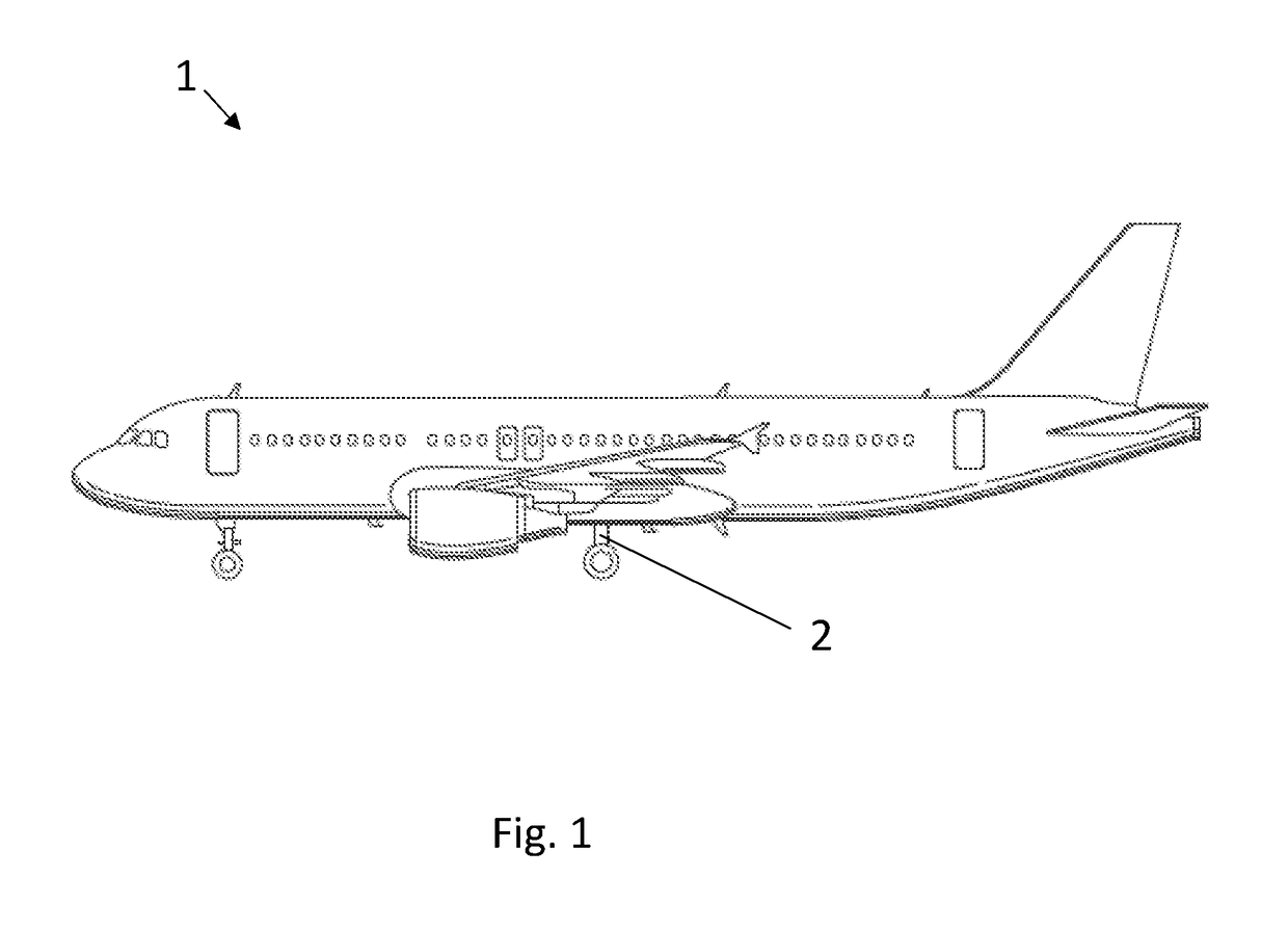
[0050]FIG. 1 shows an aircraft 1 comprising a main landing gear 2 in accordance with a first example embodiment of the invention.

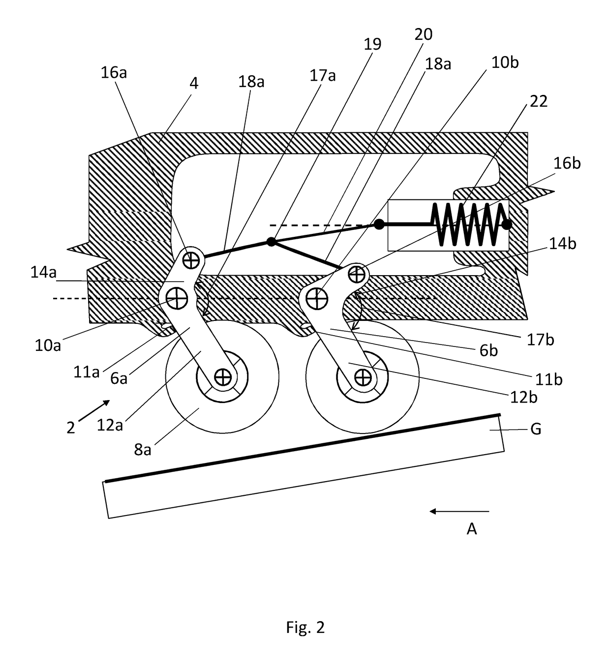
[0051]FIG. 2 shows a close up and schematic view of part of the airframe 4 and the landing gear 2 of the aircraft 1 of the first example embodiment immediately before the aircraft 1 contacts the ground, which is labelled G in FIG. 2. The forward direction of travel of the aircraft 1 is indicated with an arrow labelled A in FIG. 2. The arrow A points to the left in FIG. 2. The landing gear 2 comprises a first arm 6a mounted on a pivot 10a. A first part 12a of the arm 6a extends downwards and rearward (towards the right of FIG. 2) between the pivot 10a and a front wheel 8a. A second part 14a of the arm extends away from the pivot 10a, upwards and to the right of FIG. 2. An included link angle 17a may be defined between the two parts 12a, 14a. A link 18a is connected to the distal end of the second part 14a of the first arm 6a via a pivot 16a. The front of th...


PUM


Abstract

An aircraft landing gear 2 is disclosed having a first arm 6a configured to have one or more wheels 8a mounted at one end, the first arm 6a being configured for mounting to a pivot 10a. The landing gear 2 includes a second arm 6b configured to have one or more wheels 8b mounted at one end, the second arm 6b being configured for mounting to a pivot 10b. The landing gear 2 further includes a first link 18a pivotally coupled to the first arm 6a, a second link 18b pivotally coupled to the second arm 6b; and a main link 20 pivotally coupled to each of the first and second links 18a, 18b and to a shock absorber 22 arranged to provide a biasing force via (i) the main linkage 20 and the first link 18a which opposes rotation of the first arm 6a about the pivot 10a and (ii) the main linkage 20 and the second link 18b which opposes rotation of the second arm 6b about the pivot 10b.

Description

BACKGROUND OF THE INVENTION[0001]The present invention concerns aircraft landing gear. More particularly, but not exclusively, this invention concerns twin arm landing gear and methods of reacting landing gear loads using such a landing gear. The invention also concerns a wing assembly and an aircraft including such a landing gear.[0002]Composites are increasingly used in aircraft in view of their potential to offer weight-saving and thereby increase fuel efficiency. However, many landing gear arrangements are unsuitable for use with composite aircraft structures, for example composite wings and / or fuselages, due to the typically anisotropic load carrying ability of composite structures. This may result in composite materials having a lower load bearing capacity for similar sized structures when compared to metal structures. In particular, composite structures have a more limited capacity to react large point forces that may be transmitted to the airframe by the landing gear on land...

Claims


Application Information

Patent Timeline
IPC IPC(8): B64C25/20B64C25/62B64C25/12
CPCB64C25/20B64C25/62B64C25/12B64C2025/125B64C25/34B64C25/10B64C25/58
Inventor THOMPSON, ROBERT IAN
Owner AIRBUS OPERATIONS LTD
Why Eureka
Try Eureka