Methods of cooling process chamber components

a technology of cooling process chamber and components, applied in the direction of machine operation mode, lighting and heating apparatus, and the details of the semiconductor/solid-state device, can solve the problems of increasing the downtime of processing equipment, parts of the showerhead to debond, and components may incur damage, so as to reduce the amount of heat and reduce the power provided

Active Publication Date: 2012-11-01
APPLIED MATERIALS INC
View PDF1 Cites 234 Cited by
  • Summary
  • Abstract
  • Description
  • Claims
  • Application Information

AI Technical Summary

Benefits of technology

[0007]Methods for cooling process chamber components are provided herein. In some embodiments, a method of cooling a process chamber component may include reducing a power provided to a heater disposed proximate a surface of the process chamber component to reduce an amount of heat provided to the component by the heater; providing a coolant to coolant channels disposed within the process chamber component using a pulsed flow having a duty cycle until the process chamber component reaches a temperature that is less than or equal to a predetermined magnitude above a temperature of the coolant; and after the process chamber component reaches the temperature less than or equal to the predetermined magnitude above a temperature of the coolant, reducing the duty cycle of the pulsed flow of the coolant to zero.

Problems solved by technology

However, the inventors have observed when the component is cooled too rapidly, the component may incur damage.
For example, when cooling a two piece showerhead having multiple parts (e.g. a body and faceplate) with different coefficients of thermal expansion coupled together via a bonding material, rapid cooling of the showerhead may unduly strain or stress the bonding material, causing the parts of the showerhead to de-bond.
However, cooling in such a manner is labor intensive and / or slow, leading to increased downtime of processing equipment and decreased efficiency of processing systems.

Method used


Image

  • Methods of cooling process chamber components
  • Methods of cooling process chamber components
  • Methods of cooling process chamber components

Examples


Embodiment Construction

[0017]The present invention provides methods of cooling a process chamber component. Embodiments of the inventive methods may advantageously allow chamber components to be cooled at a sufficient rate to prevent damage to the component while not requiring continuous monitoring by a user.

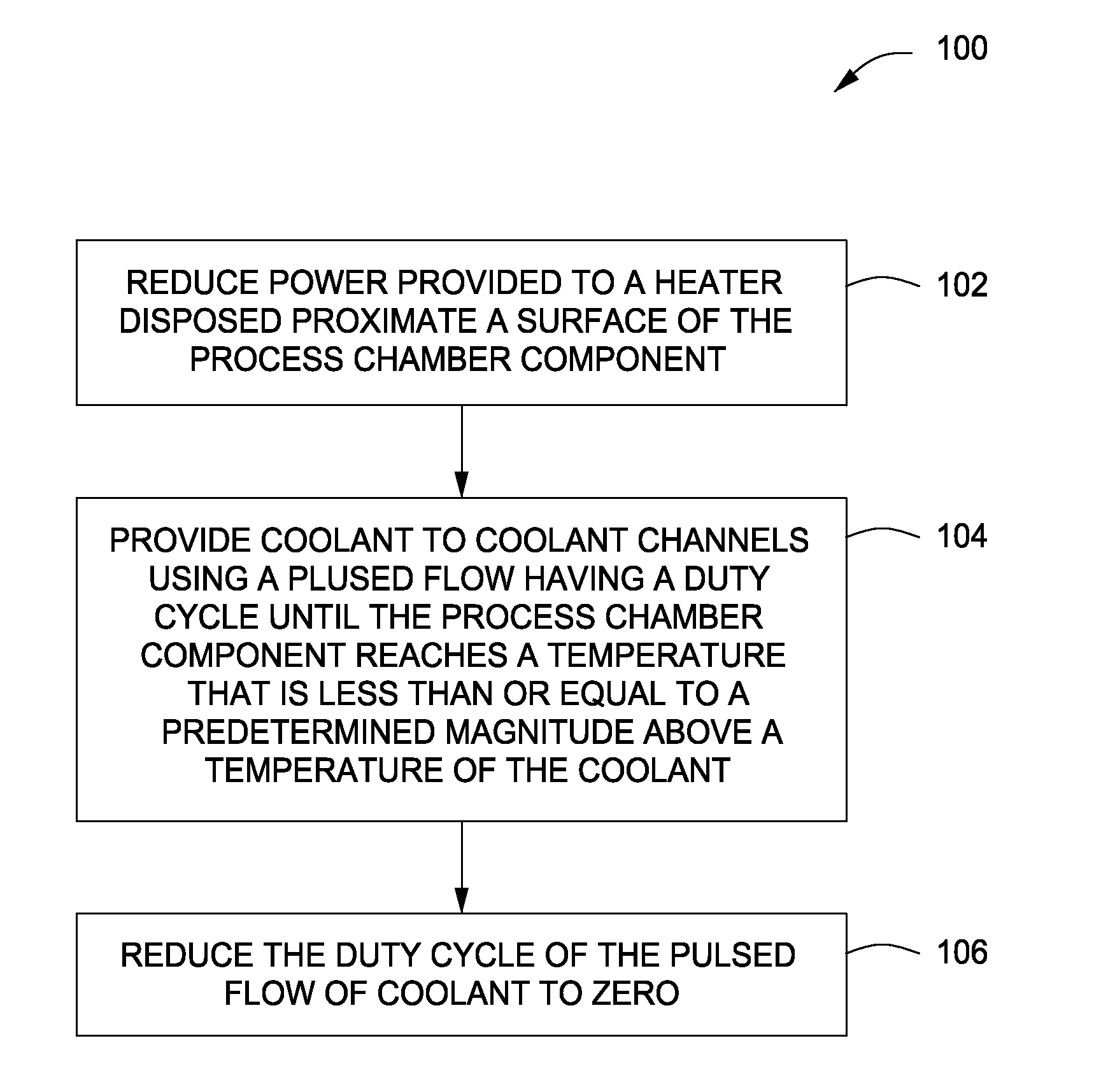
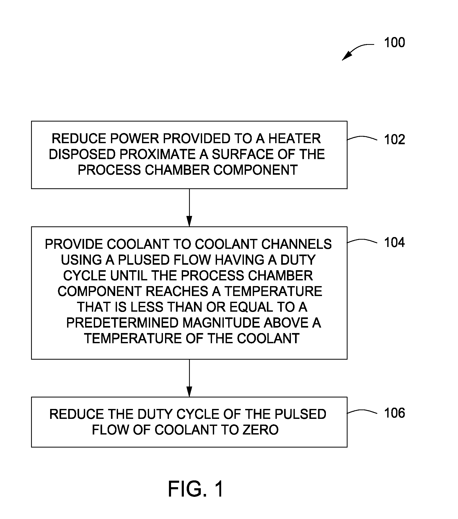
[0018]FIG. 1 depicts a method of cooling a process chamber component in accordance with some embodiments of the present invention. The method 100 may be performed in any process chamber utilized in any substrate process, for example, such as the process chamber 300 described below with respect to FIG. 3. In addition, the method 100 may be performed at any time where cooling of a process chamber component is needed. For example, in some embodiments, the method 100 may be performed to cool a process chamber component for maintenance, service, idle time, or the like after a process is finished in the process chamber or the process chamber is in an “offline state” (i.e. no process is being performed and / o...


PUM


Abstract

Methods for cooling process chamber components are provided herein. In some embodiments, a method of cooling a process chamber component may include reducing a power provided to a heater disposed proximate a surface of the process chamber component to reduce an amount of heat provided to the component by the heater; providing a coolant to coolant channels disposed within the process chamber component using a pulsed flow having a duty cycle until the process chamber component reaches a temperature that is less than or equal to a predetermined magnitude above a temperature of the coolant; and after the process chamber component reaches the temperature less than or equal to the predetermined magnitude above a temperature of the coolant, reducing the duty cycle of the pulsed flow of the coolant to zero.

Description

CROSS-REFERENCE TO RELATED APPLICATIONS[0001]This application claims benefit of U.S. provisional patent application Ser. No. 61 / 480,560, filed Apr. 29, 2011, which is herein incorporated by reference.FIELD[0002]Embodiments of the present invention generally relate to substrate processing equipment.BACKGROUND[0003]Process chambers utilized in substrate processing typically comprise a number of internal components that are repeatedly heated and cooled during and after processes are performed. In some instances, for example, when routine service or maintenance is needed after a process has been performed in a process chamber, the components are cooled to about room temperature.[0004]In temperature controlled components, for example, such as process chamber showerheads having coolants channels, to cool the component from a typical operating temperature (e.g. about 90 degrees Celsius), a heat source that heats the component may be shut off and a coolant is flowed through the coolant chan...

Claims


Application Information

Patent Timeline
Patent Type & Authority Applications(United States)
IPC IPC(8): F25B29/00
CPCH01L21/67109H01J37/32522H01J37/3244H01L2924/0002H01L2924/00H01L23/473H01L23/34
Inventor MAHADESWARASWAMY, CHETAN
Owner APPLIED MATERIALS INC
Why Eureka
Try Eureka