Planetary Resistance Welding Device And Methods Therefor

a technology of resistance welding and planetary arc welding, which is applied in the field of welding, can solve the problems of not being able to fully automate orbital arc welding, requiring significant user experience, and not being able to quickly join relatively thin metal structures. , the effect of reducing the number of welding holes

Active Publication Date: 2012-11-01
THERMAL STRUCTURES
View PDF26 Cites 5 Cited by
  • Summary
  • Abstract
  • Description
  • Claims
  • Application Information

AI Technical Summary

Benefits of technology

[0008]The present invention is drawn to configurations and methods of resistance welding in which a sheet of relatively thin or curved (or otherwise shaped) materials can be welded to a conductive tube, cylinder, or otherwise curved material. Most typically contemplated devices will use a first element (e.g., mandrel) that conductively engages with the conductive tube or cylinder, and a wheel-shaped electrode that moves about the circumference of the metallic tube in an orbital manner.
[0009]In one aspect of the inventive subject matter, a resistance welding device includes a first element with a first electrode, wherein the first element is configured to receive and conductively retain at least a portion of a first curved work piece and that is further configured to allow placement of a second work piece into a position that allows resistance welding of the first curved work piece to a second curved work piece. The welding device further includes a second element with a second electrode, wherein the second element is operationally coupled to the first element such that the second element is circumferentially movable about the first element, and such that the first and second electrodes allow for contact with the first and second work pieces during circumferential movement for resistance welding of the first curved work piece to the second curved work piece.
[0010]While not limiting to the inventive subject matter, it is typically preferred that the first element is static, and / or that the first element has a shape that allows mating engagement with an inner surface of the first work piece (e.g., having tubular / cylindrical shape). In further preferred aspects, the second electrode comprises a wheel-shaped electrode. It is also generally preferred that the second element is operationally coupled to the first element such that the second element is circumferentially movable about the first element in an amount of at least 120 degrees, and more preferably at least 360 degrees. While such coupling may be achieved in numerous manners, it is typically preferred that the second electrode is movable in an orbital fashion about the first element (e.g., using an orbital gear set).
[0011]Therefore, and viewed from a different perspective, resistance welding devices according to the inventive subject matter preferably include a first and a second electrode, wherein the second electrode has a wheel-shape and is operationally coupled to the first electrode such as to allow orbital movement of the second electrode around the first electrode. First and second electrodes are positioned relative to each other in such devices to allow resistance welding of a curved work piece to a tubular work piece. In especially preferred aspects, the first electrode is static and / or is coupled to the second electrode via an orbital gear set. Therefore, continuous resistance welding is possible, even where the curved work piece is a tubular or cylindrical work piece.
[0012]Consequently, a method of resistance welding is contemplated in which in one step at least a portion of a first curved work piece is conductively coupled to a first element that includes a first electrode. In another step, a second work piece is positioned relative to the first work piece to allow resistance welding of the first curved work piece to the second curved work piece, and in yet another step, a second electrode is circumferentially moved about the first element while welding the first curved work piece to the second curved work piece. Most typically, the second electrode is operationally coupled to the (preferably static) first element to allow circumferential movement of the second electrode about the first element. It is also generally preferred that the first element has a shape that allows mating engagement with an inner surface of the first work piece. While not limiting to the inventive subject matter, it is contemplated that the second electrode is operationally coupled to the first element (e.g., via an orbital gear set) such that the second electrode is circumferentially movable about the first element in an amount of at least 120 degrees, and more preferably at least 360 degrees.
[0013]Various objects, features, aspects and advantages of the inventive subject matter will become more apparent from the following detailed description of preferred embodiments, along with the accompanying drawing figures in which like numerals represent like components.

Problems solved by technology

However, fully automated orbital arc welding is often limited to specific welding methods (commonly TIG) and requires significant user experience.
Moreover, arc welding is often not suitable or desirable for rapid joining of relatively thin metal structures.
Still further, friction stir welding requires significant forces and is thus often not suitable for field use.
Moreover, due to the significant forces, relatively thin metal structures will typically deform under the severe process conditions.
While resistance welding is relatively simple for flat and thin work pieces, resistance welding of curved materials to curved, and especially tubular materials is often challenging.
Such problems are further compounded where the curved materials require continuous weld seams rather than weld spots.
However, such an electrode assembly is generally limited to resistance welding of flat objects.
While such configurations and methods advantageously simplify the welding process, they are typically not suitable to join two cylindrical structures end-to-end.
While such arrangement allows circumferential welding, various disadvantages nevertheless remain.
For example, due to the placement and operation of the electrodes, two welds are simultaneously created that are 180° apart, which may lead to misalignment of the welds.
Moreover, such weld devices are once again generally not suitable for joining tubular structures end-to-end or joining tubular structures to thin metal sheets.

Method used


Image

  • Planetary Resistance Welding Device And Methods Therefor
  • Planetary Resistance Welding Device And Methods Therefor
  • Planetary Resistance Welding Device And Methods Therefor

Examples


Embodiment Construction

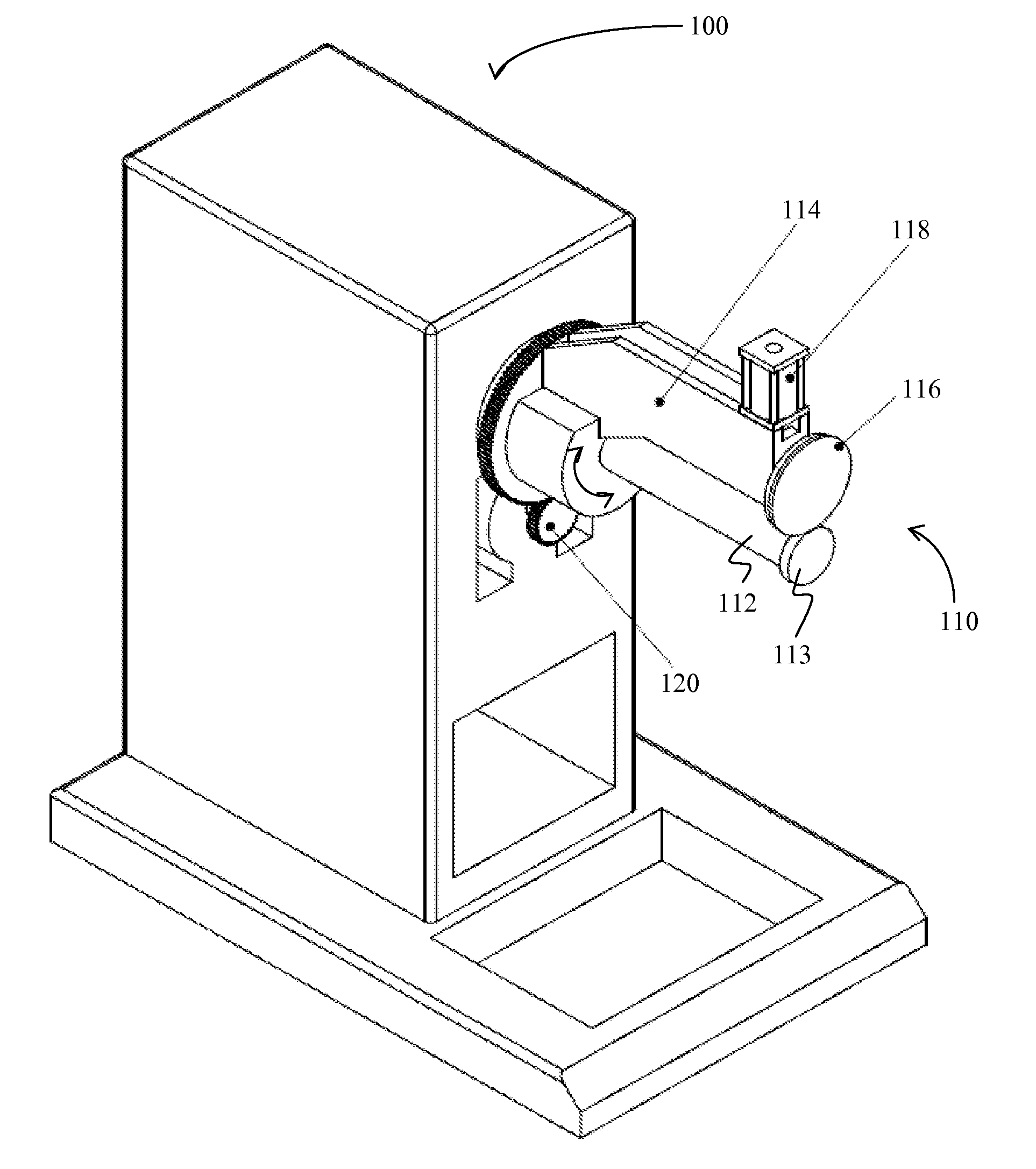
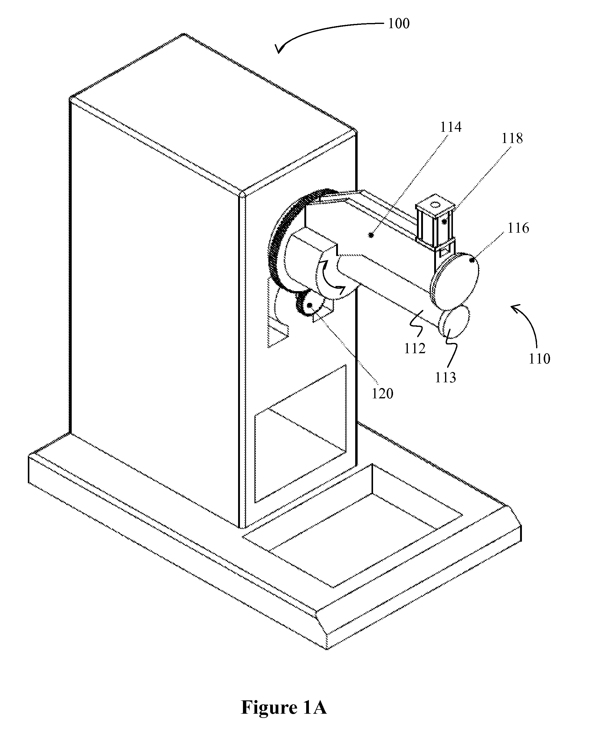
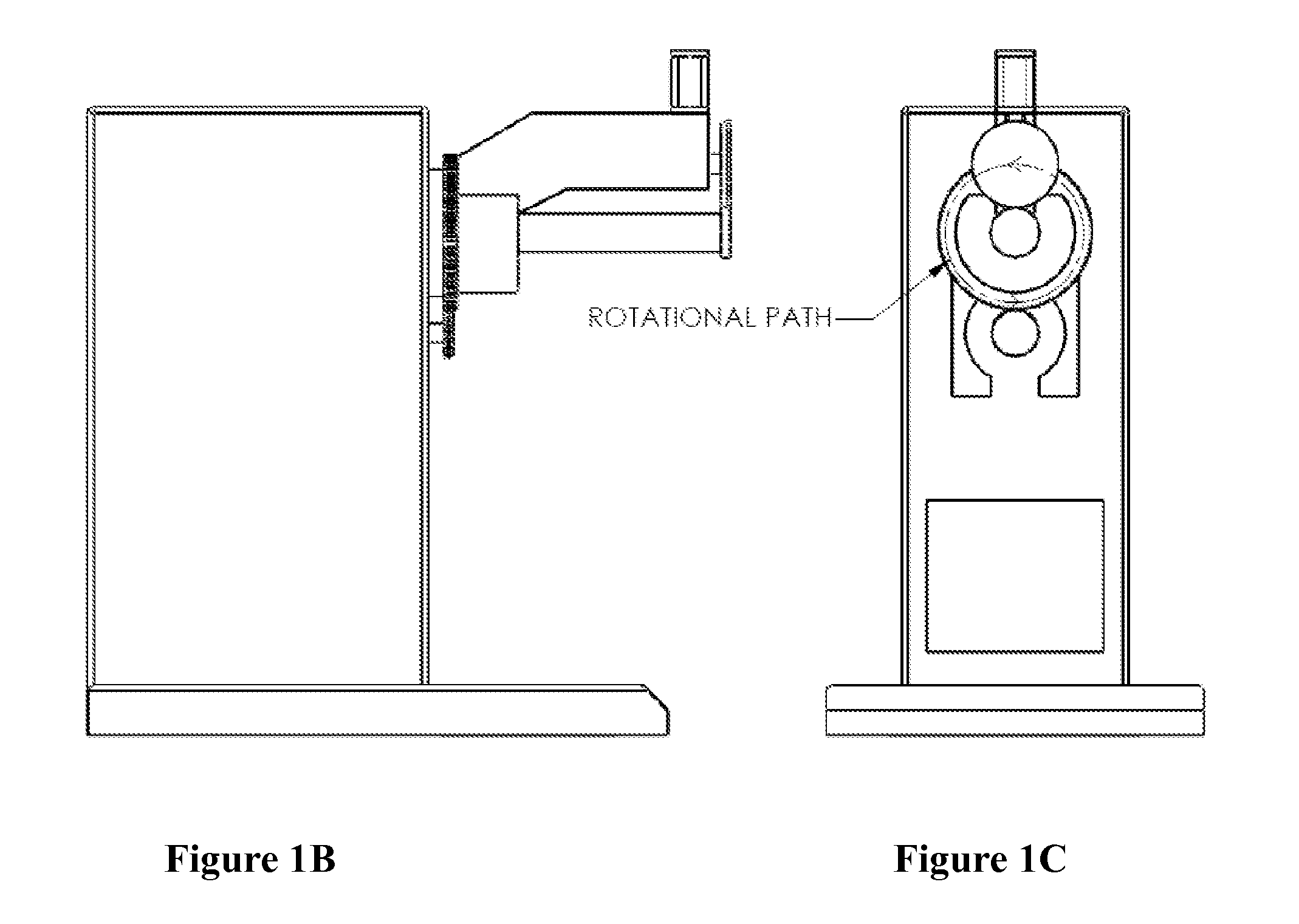
[0018]The inventor has discovered that a thin metal structure can be resistance welded to the outer surface of a tubular or cylindrical metal tube in a conceptually straightforward manner using a relatively simple welding device. Most typically, contemplated resistance welding devices will include a static and central first element having a first electrode that retains and / or conductively contacts the tube or cylinder. A second element with a wheel-shaped electrode then moves circumferentially / orbitally about the first element while the second electrode contacts the work piece that is to be welded to the tube or cylinder.

[0019]An exemplary device is schematically shown in FIG. 1A, where resistance welding device 100 includes an electrode assembly 110, comprising a preferably static, non-rotating first element 112 (in shape of a mandrel) to which an electrode 113 (preferably circular) is coupled. It is further preferred that a free spinning wheel-shaped electrode 116 is mounted on th...


PUM

PropertyMeasurementUnit
resistanceaaaaaaaaaa
shapeaaaaaaaaaa
pressureaaaaaaaaaa

Abstract

Devices and methods are contemplated in which a first electrode is circumferentially movable about a second electrode such that a tubular work piece can be resistance welded to a second work piece. Most preferably, the first electrode is a wheel-shaped electrode, while the second electrode is static and disk-shaped.

Description

[0001]This application claims priority to our copending US provisional patent application with the Ser. No. 61 / 239,716, which was filed Sep. 3, 2009 and is incorporated by reference in its entirety.FIELD OF THE INVENTION[0002]The field of the invention is welding, especially as it relates to devices and methods of welding materials to tubular structures.BACKGROUND OF THE INVENTION[0003]Welding of cylindrical structures is well known and the particular materials and uses of the welded materials will often dictate the manner of welding. For example, where high-pressure vessels or pipes are welded, manual or partially automated arc welding processes (e.g., GMAW, GTAW, SMAW, etc.) are often employed. Alternatively, and especially for pipes with moderate diameters, fully automated orbital arc welding is also known. However, fully automated orbital arc welding is often limited to specific welding methods (commonly TIG) and requires significant user experience. Moreover, arc welding is oft...

Claims


Application Information

Patent Timeline
Patent Type & Authority Applications(United States)
IPC IPC(8): B23K11/06
CPCB23K11/065B23K11/002
Inventor BARNES, VAUGHN V.
Owner THERMAL STRUCTURES
Why Eureka
Try Eureka