Surface-Mounted Microphone Arrays on Flexible Printed Circuit Boards

a flexible printed circuit board and microphone technology, applied in the field of audio engineering, can solve the problem of limiting the array geometry to planar configurations of the array manifold

Active Publication Date: 2012-11-01
MH ACOUSTICS
View PDF7 Cites 49 Cited by
  • Summary
  • Abstract
  • Description
  • Claims
  • Application Information

AI Technical Summary

Benefits of technology

[0007]Problems in the prior art are addressed in accordance with the principles of the present invention by mounting microphone devices on flexible PCBs that are now used in miniaturized product design and as interconnects in complex multi-board systems, to allow more-general microphone array geometries. For example, mounting inexpensive, small, surface-mount MEMS or electret microphone devices in certain configurations on flexible PCBs can be used to realize high-quality, professional-grade, directional microphone arrays.

Problems solved by technology

Conventional, rigid PCB technology, however, limits the array geometry to planar configurations for the array manifold.

Method used


Image

  • Surface-Mounted Microphone Arrays on Flexible Printed Circuit Boards
  • Surface-Mounted Microphone Arrays on Flexible Printed Circuit Boards
  • Surface-Mounted Microphone Arrays on Flexible Printed Circuit Boards

Examples


Embodiment Construction

Flexible PCBs and Microphone Arrays

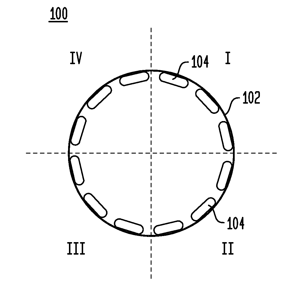
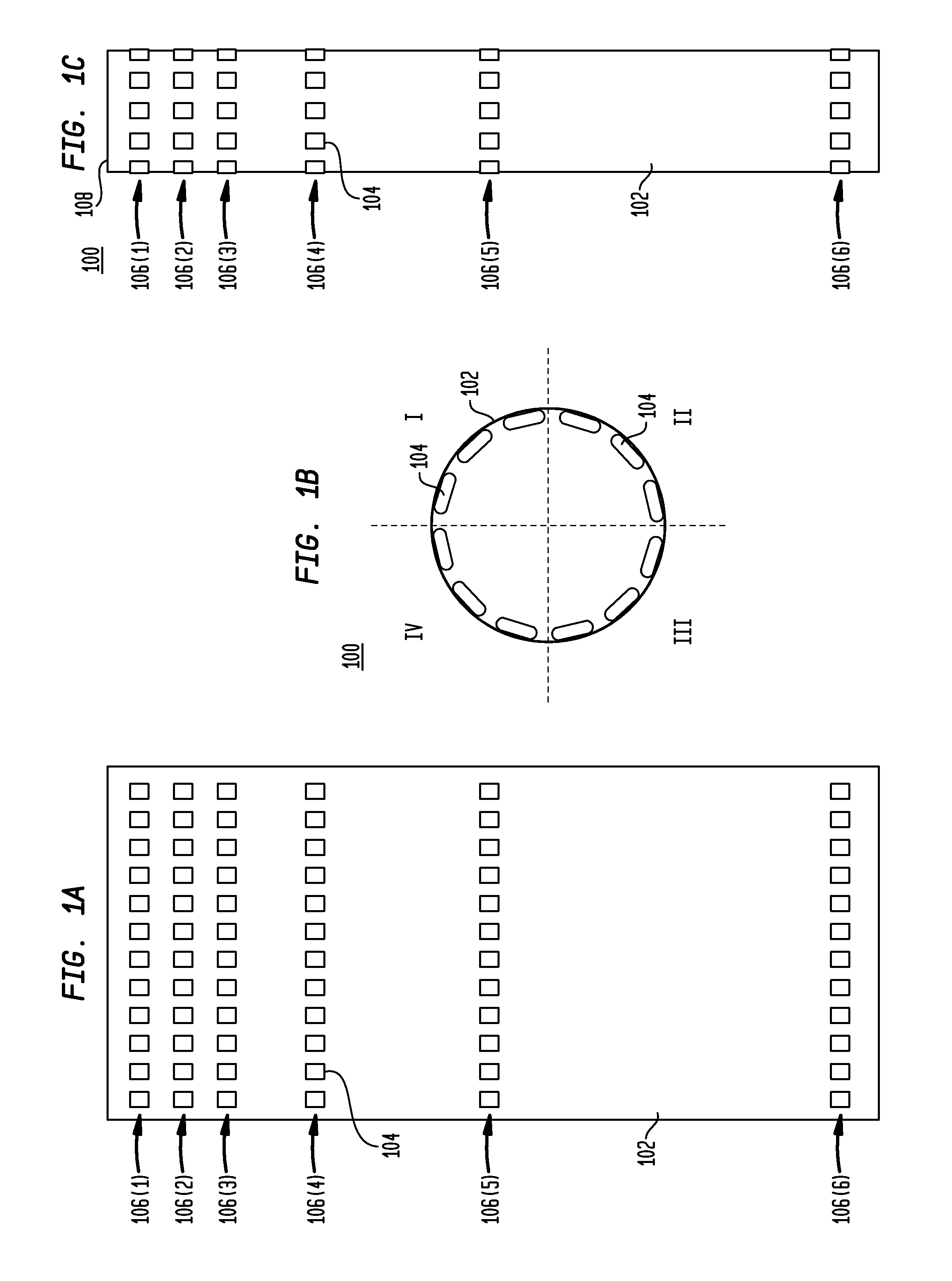
[0017]Flexible PCB technology using layers of copper traces and insulating films have become a standard way for designers to connect other subsystems needing a large number of connections in tight spaces. Miniaturized devices use this technology to pack the entire volume of the device as much as possible.

[0018]Flexible PCBs have layers of copper wedged in between layers of insulating film. The insulating layers are commonly made from polyimide films, such as (but not limited to) Kapton® polyimide films from DuPont of Wilmington, Del. Flexible PCBs can currently be made with up to about six layers, with the bending stiffness increasing as the number of layers increases.

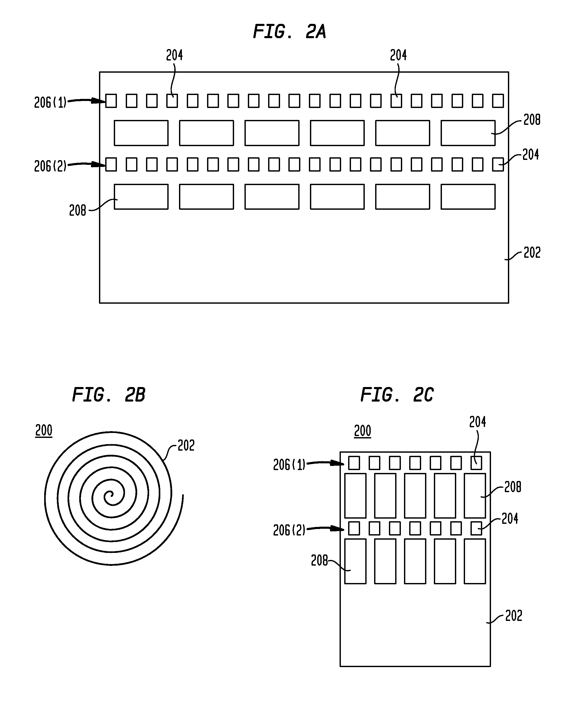
[0019]Flexible PCBs can be populated with components using standard pick-and-place PCB-manufacturing equipment. Solder connection of the components to the boards is also done in a similar manner as for conventional, rigid PCBs. Flexible PCBs can be entirely flexible or can contain bot...


PUM


Abstract

A microphone array, having a three-dimensional (3D) shape, has a plurality of microphone devices mounted onto (at least one) flexible printed circuit board (PCB), which is bent to achieve the 3D dimensional shape. Output signals from the microphone devices can be combined (e.g., by weighted or unweighted summation or differencing) to form sub-element output signals and / or element output signals, and ultimately a single array output signal for the microphone array. The PCB may be uniformly flexible or may have rigid sections interconnected by flexible portions. Possible 3D shapes include (without limitation) cylinders, spirals, serpentines, and polyhedrons, each formed from a single flexible PCB. Alternatively, the microphone array may be an assembly of multiple, interconnecting sub-arrays, each having two or more rigid portions separated by one or more flexible portions, where each sub-array has at least one cut-out portion for receiving a rigid portion of another sub-array.

Description

CROSS-REFERENCE TO RELATED APPLICATIONS [0001]This application claims the benefit of the filing dates of U.S. provisional application No. 61 / 289,033, filed on Dec. 22, 2009 as attorney docket no. 1053.012PROV1, and U.S. provisional application No. 61 / 299,019, filed on Jan. 28, 2010 as attorney docket no. 1053.012PROV2, the teachings of both of which are incorporated herein by reference in their entirety.BACKGROUND[0002]1. Field of the Invention[0003]The present invention relates to audio engineering and, more specifically but not exclusively, to microphone arrays.[0004]2. Description of the Related Art[0005]This section introduces aspects that may help facilitate a better understanding of the invention. Accordingly, the statements of this section are to be read in this light and are not to be understood as admissions about what is prior art or what is not prior art.[0006]With the recent availability of inexpensive, small, surface-mount MEMS (microelectromechanical systems) and elect...

Claims


Application Information

Patent Timeline
Patent Type & Authority Applications(United States)
IPC IPC(8): H04R3/00
CPCH04R19/016H04R19/01H04R1/04H04R3/005H04R2201/003H04R2430/23
Inventor ELKO, GARY W.
Owner MH ACOUSTICS
Why Eureka
Try Eureka