

Driving assist device
a technology of assist device and driving lane, which is applied in the direction of steering initiation, vessel construction, instruments, etc., can solve the problem of reducing the reliability of the result of driving lane determination
- Summary
- Abstract
- Description
- Claims
- Application Information
AI Technical Summary
Benefits of technology
Problems solved by technology
Method used
Image

Examples
embodiment 1
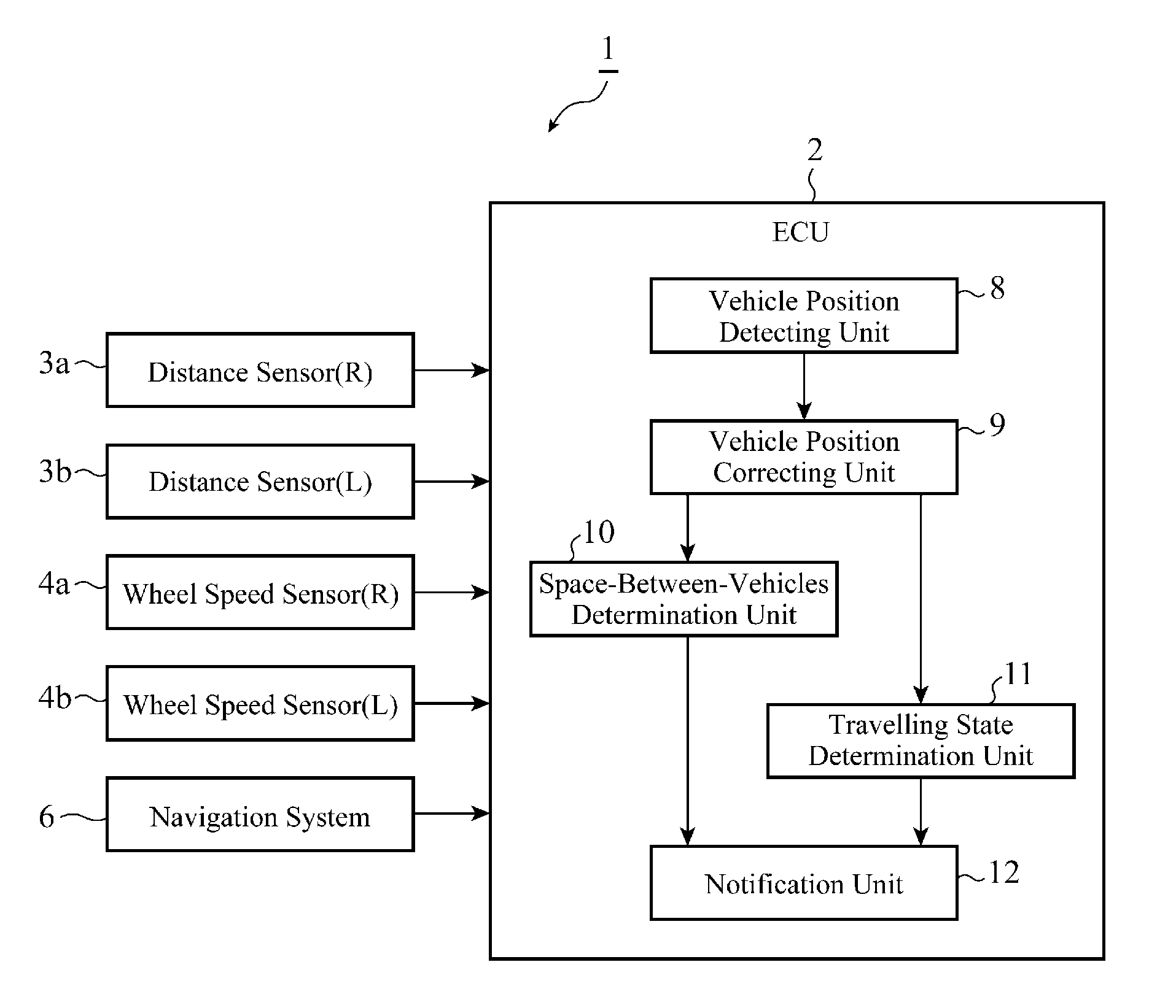
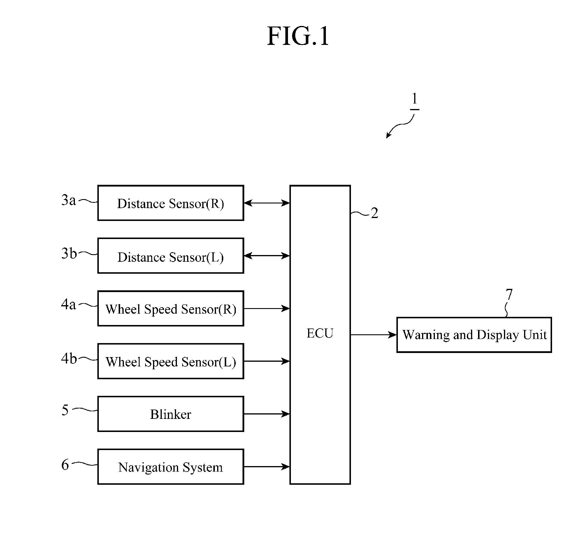
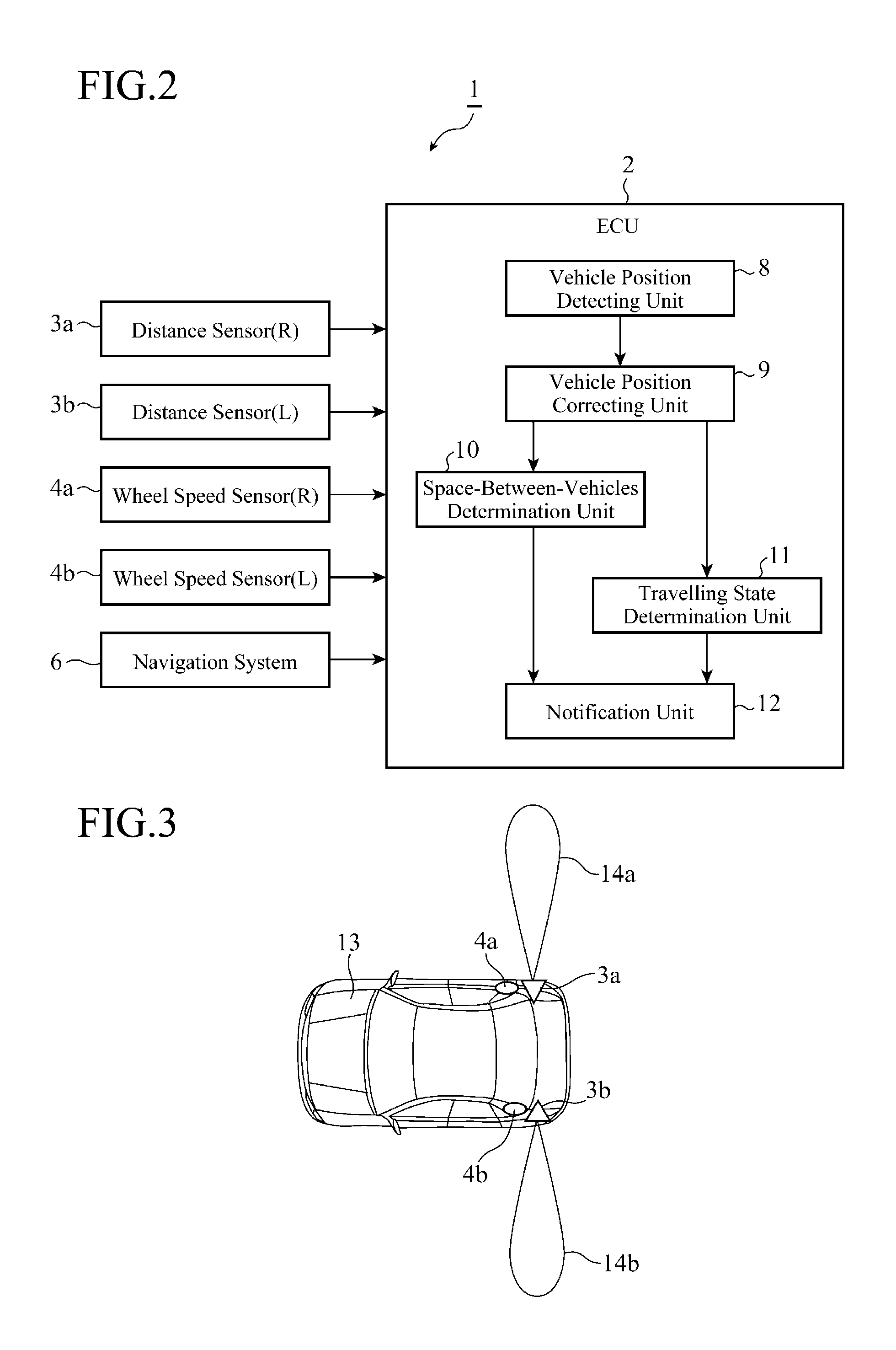
[0023]FIG. 1 is a view showing the structure of a driving assist system in accordance with the present invention. Referring to FIG. 1, the driving assist system 1 is provided with a driving assist device which is constructed in an ECU (Electric Control Unit) 2 which carries out electronic control in a vehicle, distance sensors 3a and 3b, wheel speed sensors 4a and 4b, a blinker 5, a navigation system 6, and an output unit 7. The distance sensors 3a and 3b are disposed on right and left side surfaces of a front portion or a rear portion of the vehicle, and each of the distance sensors applies a detection wave and receives a reflected wave of the detection wave from an object to be detected to detect the distance between the sensor and the object to be detected. As the detection wave, an ultrasonic wave, a laser beam, a radio wave, or the like is provided.
[0024]The wheel speed sensors 4a and 4b are disposed for the right and left rear wheels of the vehicle, respectively, and each of t...
embodiment 2
[0074]While a driving assist device in accordance with this Embodiment 2 fundamentally has the same structure as that in accordance with Embodiment 1, a travelling state determination unit in accordance with this Embodiment 2 differs from that in accordance with Embodiment 1 in that the travelling state determination unit determines whether or not a vehicle is travelling in a zigzag direction, i.e., being in a so-called “unsteady travelling” state as a travelling state of the vehicle. Therefore, refer to FIG. 2 for information about the structure of the driving assist device in accordance with Embodiment 2.
[0075]FIG. 12 is a view for explaining a process of determining the travelling state which is carried out by the travelling state determination unit 11 in accordance with Embodiment 2. The travelling state determination unit 11 successively receives distance data showing the position of the vehicle in a direction of the width of the road which is corrected by a vehicle position co...
embodiment 3
[0082]While a driving assist device in accordance with this Embodiment 3 fundamentally has the same structure as that in accordance with Embodiment 1, a vehicle position correcting unit in accordance with this Embodiment 3 differs from that in accordance with Embodiment 1 in that when a reflected wave is frequently observed through a one-time transmission of ultrasonic waves from ultrasonic sensors disposed on right and left sides of a vehicle, the driving assist device sets the reception sensitivity of each of the ultrasonic sensors to low while setting the transmission sensitivity of each of the ultrasonic sensors to high, and, when the speed of the vehicle is higher than a predetermined speed, sets the transmission and reception sensitivities of each of the ultrasonic sensors to high. Therefore, refer to FIG. 3 for information about the structure of the driving assist device in accordance with Embodiment 3.
[0083]FIG. 13 is a view for explaining adjustment of the transmission sens...
PUM
 Abstract
Description
Claims
Application Information