
Floating support structure for a solar panel array

a solar panel array and floating support technology, applied in the direction of heat collector mounting/support, pv power plants, lighting and heating apparatus, etc., can solve the problems of increasing the cost of land (the ground itself) and causing damage, and ensuring the safety of the environmen

Inactive Publication Date: 2012-11-08
SPG SOLAR
View PDF0 Cites 35 Cited by
  • Summary
  • Abstract
  • Description
  • Claims
  • Application Information

AI Technical Summary

Benefits of technology

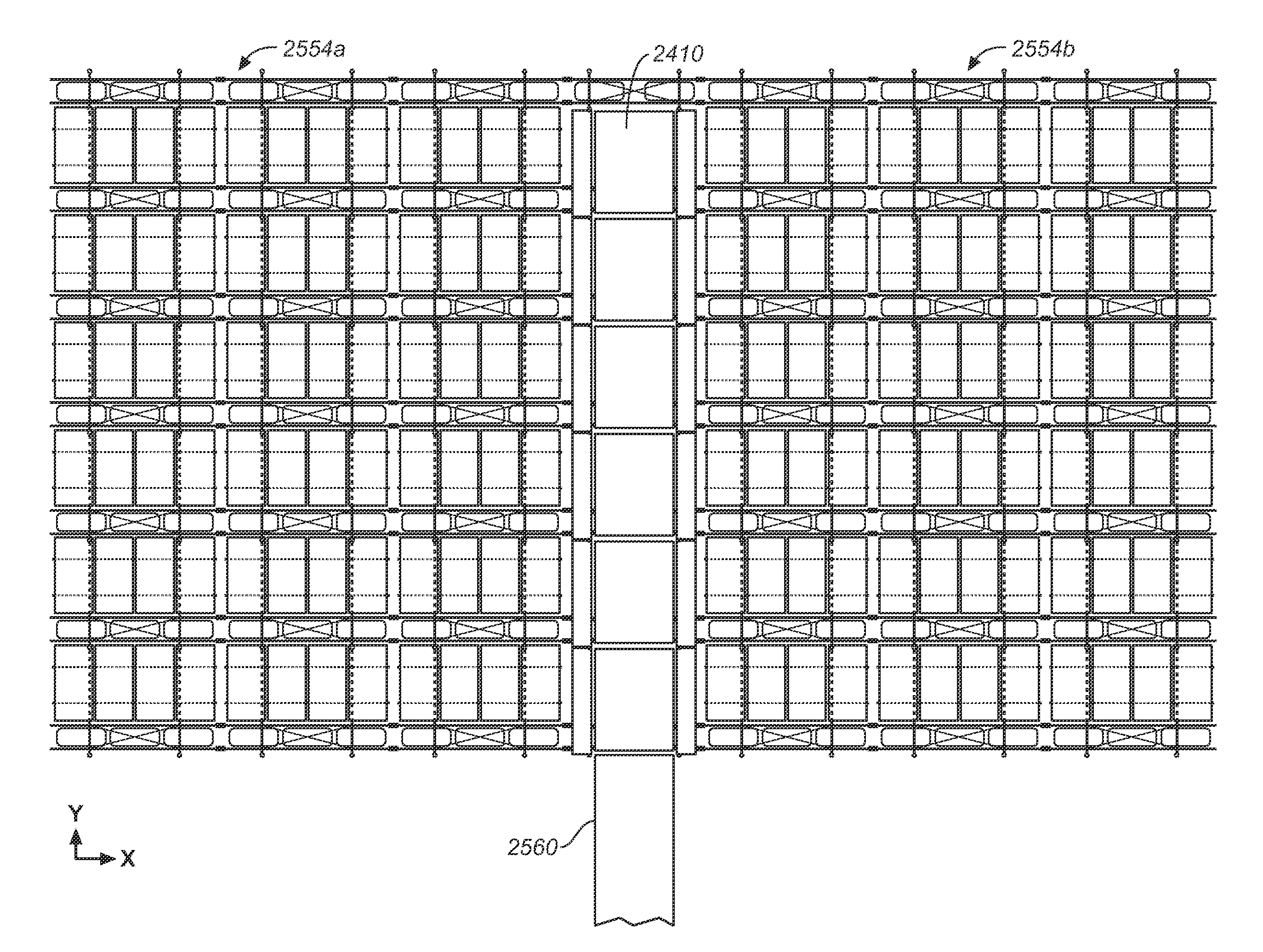
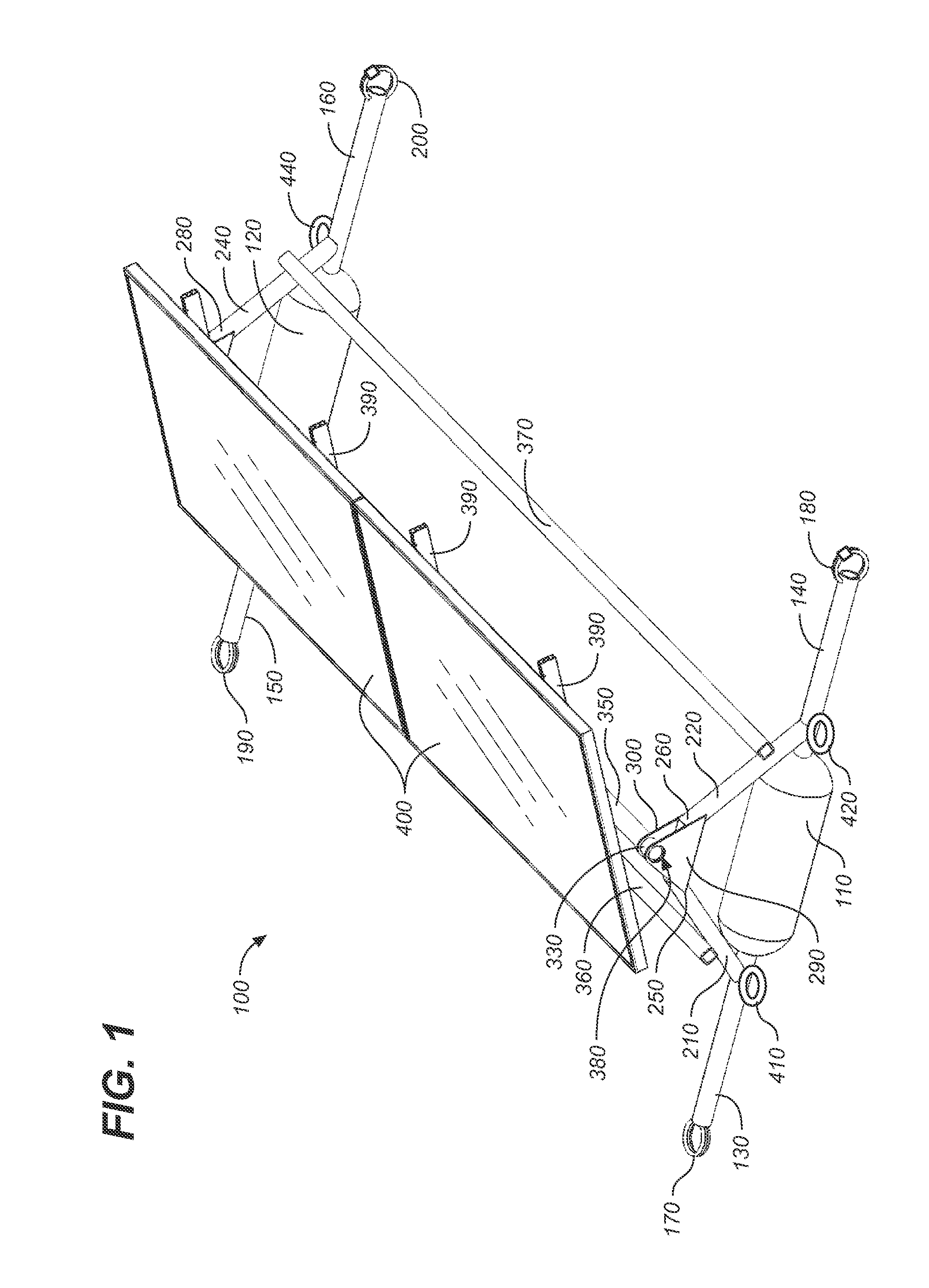
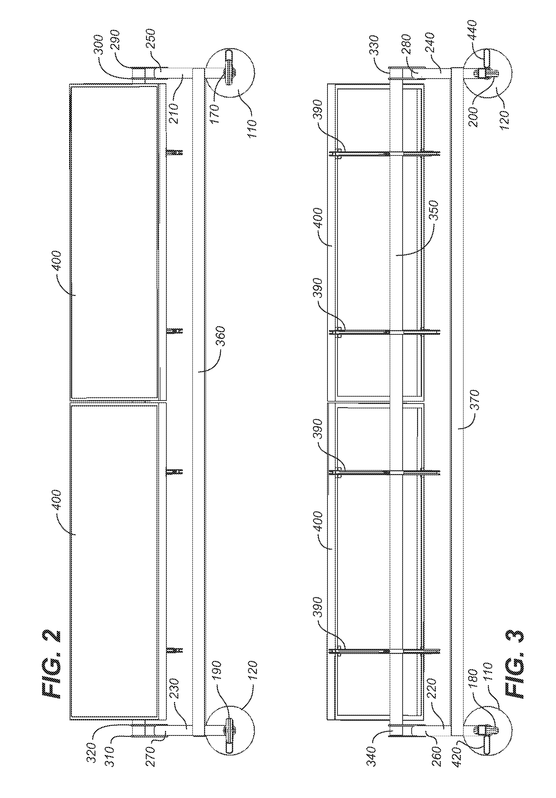
[0009]The present invention is a floating support structure for solar panels and / or concentration collectors. The invention provides the means to mount an array of solar panels or other PV or thermal elements on modular floating platforms joined together to form an array. Such an array may include only a few array modules, or it may include many hundreds or even thousands of modules. The invention includes a system for assembling and connecting floating support modules on land for deployment onto water using a crane or roller conveyor system. The invention further includes a mooring and anchoring system for connecting an array to shore in manner that prevents overstress of the structural components comprising the array field.

Problems solved by technology

Rooftop solar arrays require the modification of the rooftop structure, can be dangerous and difficult to work on, and provide only a limited footprint.
On the other hand, land (the ground itself) is increasingly expensive and may be usefully employed for a number of purposes other than solar array installation.
Additionally, the amount of land required for a solar array that generates a productive amount of electrical power can be considerable.
Systems and apparatus specifically adapted for floating a large array of solar panels are developing, but they are relatively new and thus currently present several as yet unsolved problems.
Few practical and economically feasible systems have been disclosed; fewer still have reached the market place.
However, neither the foregoing Japanese patent application, nor any other known land based systems, provide certain critical solutions for assembling and deploying large scale arrays on water, nor does any known art teach comprehensive mooring and anchoring solutions for placement of large scale arrays on water.
The systems now known require the connection and assembly of array units on the water, and mooring systems leave large scale arrays vulnerable to damage from wind and wave action.

Method used


Image

  • Floating support structure for a solar panel array
  • Floating support structure for a solar panel array
  • Floating support structure for a solar panel array

Examples


embodiment 700

[0102]FIGS. 7-13 show a second preferred embodiment 700 of the modular floating support structure for a solar panel array of the present invention. In this alternative embodiment, the floatation elements 710 comprise an outer tube 720 having an interior wall 730 and an exterior surface 740, an inner tube 750 having an interior wall 760 and an exterior surface 770 spaced apart from the interior wall of the outer tube, and polygonal end caps 780 welded to the ends of the outer and inner tubes so as to create a watertight and airtight seal over first and second air chambers 790, 800.

[0103]The end caps 780 are preferably polygonal when viewed on end (see FIG. 7), and are conformed on an interior surface with an inner socket 810 which tightly fits over, captures, and retains an end of the inner tube 750 when welded, and an outer socket 820 which tightly fits over, captures, and retains an end of the outer tube 720 when welded. The top side 830 of the end caps essentially comprise a mount...

embodiment 1400

[0106]FIGS. 14-19 show a third preferred embodiment 1400 of the modular floating support structure for a solar panel array of the present invention. In this embodiment each of the floatation elements 1410 comprises a single substantially cylindrical tube or pipe 1420 covered with a welded cap 1430 at each end to form a watertight and airtight seal, as is well known in the art. The tubes are preferably fabricated from readily available PVC, HDPE, ABS, CPVC tubing material, though numerous other watertight materials would be perfectly suitable.

[0107]Mounting elements are disposed along the length of the floatation elements and proximate the ends. These structures include a slightly flexible metal band 1440 having ends 1450 with bolts 1460 extending therefrom. A mounting bracket 1470 is provided for placement over the top portion 1480 of the cylindrical pipe 1420. The mounting bracket 1470 includes a mounting post 1480 having an angled top 1490 with apertures for passing mounting bolts...

embodiment 2000

[0110]FIGS. 20-22 show a fourth alternative embodiment 2000 of the floatation element of the present invention. In this embodiment, the pontoon comprises doubled walled corrugated pipe having a channel or slot 2010 in each end 2020. A cylinder of foam 2030 covered by a watertight bag 2040 is inserted into the pipe and a cap 2050 placed on the end to form a watertight seal. Mounting apparatus described in connection with the third preferred embodiment may be employed for supporting a solar panel array.

[0111]FIG. 23 shows a fifth preferred embodiment of the floatation element. In this embodiment, pipe 2300 is cut along its length to provide an axial opening into which a foam insert 2310 is wedged and captured by resilient ends 2320. Again, mounting apparatus as described in connection with the third preferred embodiment may be employed for supporting a solar panel array. Alternatively, mounting apparatus may be fastened (e.g., by bolts) directly to the upper portion 2330 of the cut pi...


PUM

PropertyMeasurementUnit
Forceaaaaaaaaaa
Lengthaaaaaaaaaa
Electrical resistanceaaaaaaaaaa

Abstract

A modular floating support structure for a solar panel array, each array module including floatation elements, a framework comprising E-W frame members connected to and aligning the floatation elements as well as N-S frame members providing a base on which panel supports are installed, and coupling hardware for connecting array modules to adjoining modules in both the E-W direction and N-S direction. A wireway / walkway may be disposed between and connect two large array fields. A mooring and anchoring system secures the array to shore, distributes loads along large portions of the array, and prevents loads from being concentrated in small regions of the array, thereby preventing damage from environmental forces typically encountered in outdoor marine environments.

Description

CROSS REFERENCE TO RELATED APPLICATIONS[0001]The present application is a continuation-in-part of U.S. Utility patent application Ser. No. 11 / 861,226, filed Sep. 25, 2007 (Sep. 25, 2007), which is a continuation-in-part of U.S. patent application Ser. No. 11 / 264,285, filed Oct. 31, 2005 (Oct. 31, 2005), which claims the benefit of U.S. Provisional Patent Application Ser. No. 60 / 623,328, filed Oct. 29, 2004 (Oct. 29, 2004); and also claims the benefit of U.S. Provisional Patent Application Ser. No. 61 / 492,224 filed Jun. 1, 2011 (Jun. 1, 2011.)STATEMENT REGARDING FEDERALLY SPONSORED RESEARCH OR DEVELOPMENT[0002]Not applicable.REFERENCE TO A MICROFICHE APPENDIX[0003]Not applicable.TECHNICAL FIELD[0004]The present invention relates generally to photovoltaic power systems, and more particularly to support structures for solar photovoltaic collector panels, and still more particularly to a modular floating support structure for a solar panel array.BACKGROUND INFORMATION AND DISCUSSION OF ...

Claims


Application Information

Patent Timeline
IPC IPC(8): H01L31/048H01L31/18
CPCF24J2/541H01L31/0422Y02E10/47F24J2/5239Y10T29/49355F24J2/5267Y02E10/50H02S20/00F24S25/16F24S25/65F24S30/425F24S25/50F24S20/70
Inventor ALWITT, PHILDE MAIO, JOHNMOORE, MARKBOGART, RYANWESTBROOK, SEANTHOMPSON, DANIEL
Owner SPG SOLAR
Learn More