Data center aisle containment system utilizing a movable sash that is integral to the computer rack cabinet

a technology of computer rack cabinet and containment system, which is applied in the direction of cooling/ventilation/heating modification, electrical apparatus casing/cabinet/drawer, instruments, etc., can solve the problems of waste of energy, inefficiency of cooling air which mixes above the rack, and inefficiency of the above cold aisle system

Inactive Publication Date: 2012-11-08
NAMEK RAMZI Y +2
View PDF7 Cites 33 Cited by
  • Summary
  • Abstract
  • Description
  • Claims
  • Application Information

AI Technical Summary

Benefits of technology

[0020]A system for controlling the flow of air over the top of racks containing computer servers arrayed in rows in a room was disclosed. The system comprised: A computer rack door with openings which allow air flow through the door. Channels are attached to the sides of the door, arrayed parallel to the sides of the door, with the tops of the channels near the top of the door. A rectangular air impermeable sash was capable of mounting on the door through interaction of the side edges of the sash with the channels. The sash was vertically movable from a lower position wherein the top edge of the sash is approximately adjacent to the top edge of the door, and the upper position in which the top edge of the sash is capable of to...

Problems solved by technology

The cooling of computer servers in data centers, sometimes termed “IT or electronic servers”, presents significant problems in efficient energy consumption.
The above cold aisle—hot aisle system suffers significant inefficiencies which stem from the mixing and recirculation of air between the cold aisle and the hot aisle over the top of the racks.
The energy expended in the cooling of air which mixes above the racks is wasted, as that cooled air never is used to cool the computer servers.
The containment situation is complicated by the...

Method used


Image

  • Data center aisle containment system utilizing a movable sash that is integral to the computer rack cabinet
  • Data center aisle containment system utilizing a movable sash that is integral to the computer rack cabinet
  • Data center aisle containment system utilizing a movable sash that is integral to the computer rack cabinet

Examples


Embodiment Construction

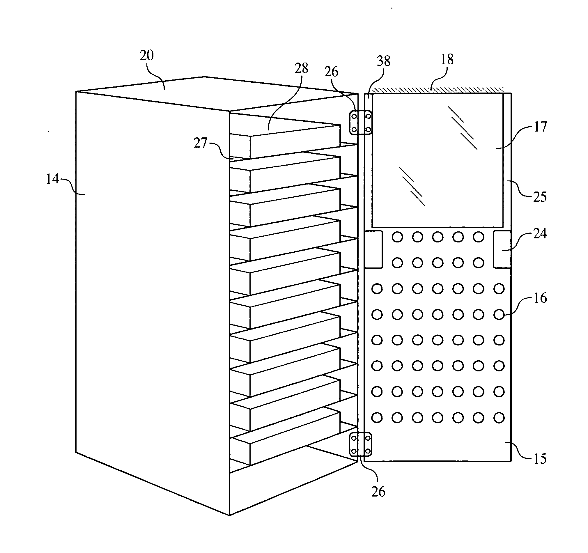
[0032]FIG. 1 is a perspective view of the interior of a data center showing an array of server racks each with a first embodiment sash system. The sash system is comprised of a sash, sash mounts, elevation mechanism, and control system. The first embodiment sash system is connected to the rack front door. Visible in FIG. 1 is the data center floor 10, the cold aisle 11 through which cooled air is delivered, and the hot aisle 12 into which air which has been used to cool the computer servers is collected. An array 13 of racks is shown comprised of a multiplicity of similar individual racks 14. Also visible is the individual rack front door 15 which has a multiplicity of ventilation holes 16, and a rack handle 23 for opening the rack front door 15. A transparent sash 17 is shown in the upper position in which it extends above the rack top 20. The top gasket 18 at the top edge 35 interacts with and has a sealing relationship with the data center ceiling (not shown in FIG. 1). A left ga...


PUM


Abstract

An embodiment includes a transparent sash mounted integral to the perforated doors on racks which hold computer servers typically installed in data centers. The racks are arrayed in rows forming cold aisles and hot aisles. Cooled air introduced into the cold aisle flows through the racks and cools the servers, and subsequently is removed from the hot aisle. Embodiment sashes slide vertically and extend above the tops of the racks and form a sealing relationship with the data center ceiling and adjacent sashes, thereby preventing wasteful mixing and recirculation of cooled and heated air over the tops of the racks. Embodiments are raised and lowered manually or automatically. The controls for the movement of the sashes are tied to the building automation and fire alarm systems and the sashes are lowered automatically upon activation of the data center fire suppression system, thereby complying with code requirements and avoiding interference with the fire sprinkler and suppression systems.

Description

BACKGROUND OF THE INVENTION[0001]1. Field of the Invention[0002]This application relates to the control and management of cooling airflow in computer data centers.[0003]2. Description of Related Art including information disclosed under 37 CFR 1.97 and 1.98[0004]The cooling of computer servers in data centers, sometimes termed “IT or electronic servers”, presents significant problems in efficient energy consumption. The computer servers typically are stacked on shelves in enclosed racks or cabinets some up to seven feet high, three feet wide, and four feet deep. Doors on the front and back sides of the racks retain the servers in the racks and control access to the servers. The front and back doors of the racks are perforated so that cooling air enters through the perforations in the front door, flows over the enclosed computer server, thereby cooling the heat generating processors, and the now heated air exits through the rear door of the rack. Racks are aligned in a data center in...

Claims


Application Information

Patent Timeline
IPC IPC(8): H05K7/20
CPCH05K7/20745
Inventor NAMEK, RAMZI Y.GALLAGHER, GERARD J.ROSATO, THOMAS
Owner NAMEK RAMZI Y
Why Eureka
Try Eureka