Overhead travelling carrige

a technology for travelling cars and carriages, which is applied in the direction of cranes, lifting devices, transportation and packaging, etc., can solve the problems of difficult to adjust the length of the hanging members, difficult to uniformly impose the load of the platform on the four hanging members, and complicated transmission mechanisms such as the gearbox, so as to achieve stable support, prevent vibration, and raise and lower

Active Publication Date: 2006-08-17
MURATA MASCH LTD
View PDF6 Cites 8 Cited by
  • Summary
  • Abstract
  • Description
  • Claims
  • Application Information

AI Technical Summary

Benefits of technology

[0011] According to the present invention, the platform is supported by the four hanging members. The two of the four hanging members are attached to the platform via the pivoting arm that is pivotable in the vertical plane. The two other hanging members are attached, for example, directly to the platform without using the pivoting arm. Thus, the platform is supported at the following three points as viewed from the platform itself: a fulcrum of the pivoting arm and the positions to which the two other hanging members are attached. Consequently, the platform can be elevated and lowered while being stably supported and prevented from vibrating.
[0012] According to the present invention, tension is always applied to the two of the four hanging members which are not attached to the pivoting arm. This is because these hanging members correspond to the support of two of the three points to be supported. Moreover, tension is always applied to the two hanging members attached to the pivoting arm. For example, if the two hanging members attached to the pivoting arm have unbalanced lengths, the pivoting arm pivots to eliminate the unbalance such as a difference in length. This allows the four hanging members to be always tensioned. The adjustment of lengths of the hanging members and the like is easy because it is basically similar to that carried out for the three-point support. For example, it is possible to adjust the two hanging members attached to the pivoting arm so that the arm extends horizontally and then to adjust the two other hanging members so that the platform lies horizontally. An arbitrary technique may be used to adjust the hanging members. In this manner, the unbalance between the hanging members is corrected by pivoting the pivoting arm. If the hanging members become unbalanced during elevation or lowering, the pivoting arm similarly pivots to absorb the unbalance.
[0013] As a result, the present invention enables the platform to be elevated and lowered while preventing the platform from vibrating. Further, the hanging members can be easily adjusted to distribute tension among them. Consequently, the hanging members can stand long use. The elevate and lower driving section side has only to wind or feed the four hanging members. This simplifies a driving mechanism.
[0014] According to the aspect of the present invention set forth in claim 2, the four hanging members each comprise a belt and are attached so that the width direction of two of these belts is parallel to the longitudinal direction of the pivoting arm. The platform is likely to vibrate in a thickness direction of the belts. When the longitudinal direction of the pivoting arm is parallel to the width direction of the belts, the pivoting arm does not vibrate even if the platform vibrates in the thickness direction of the belts. This makes it possible to reliably prevent vibration.
[0015] According to the aspect of the present invention set forth in claim 3, the four hanging members are wound around and fed from the drums having the common shaft. Thus, it is only necessary to drive the common shaft using a driving motor or the like. This particularly simplifies the structure of the elevate and lower driving section.

Problems solved by technology

This complicates a transmission mechanism such as the gearbox 84.
However, it is difficult to uniformly impose the load of the platform on the four hanging members 92.
However, with the four hanging members 92, involving an extra one point compared to the three-point support configuration, it is very difficult to adjust the lengths of the hanging members 92 and the like.
As described above, no mechanisms are known which have accomplished both objects to prevent the vibration of the platform and to simplify the driving mechanism.

Method used


Image

  • Overhead travelling carrige
  • Overhead travelling carrige
  • Overhead travelling carrige

Examples


Embodiment Construction

[0023] An optimum embodiment of the present invention will be described below.

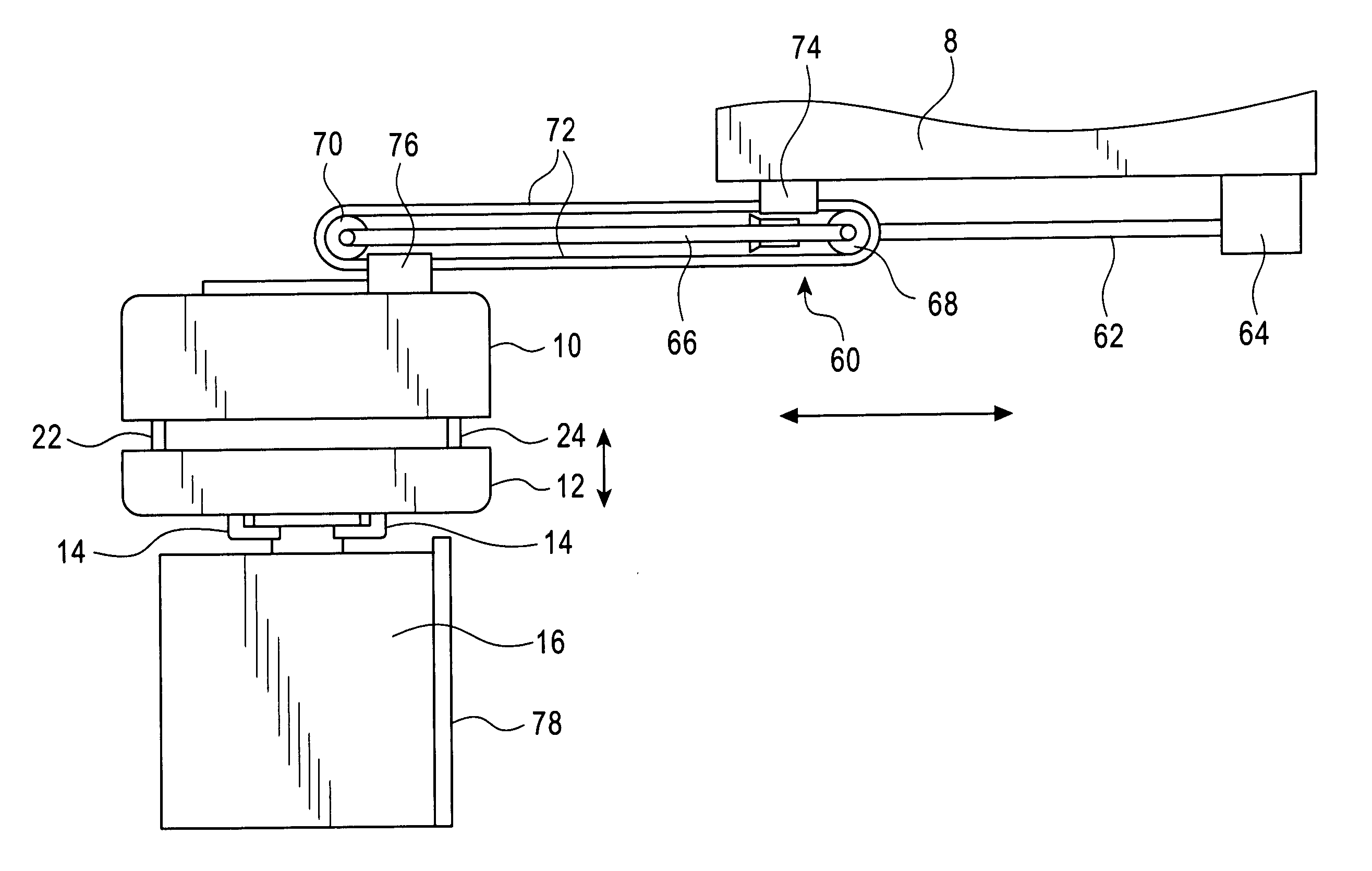
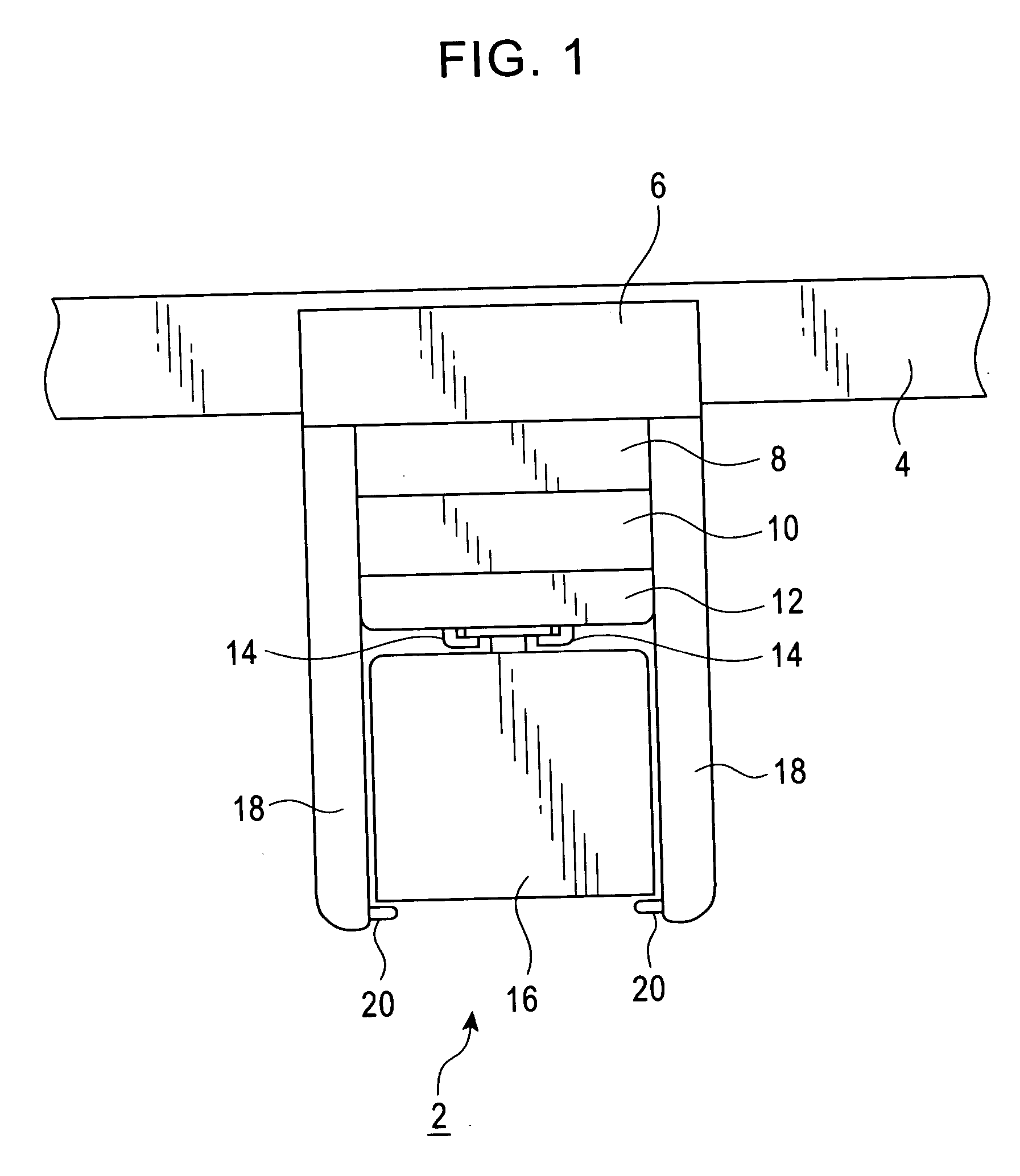
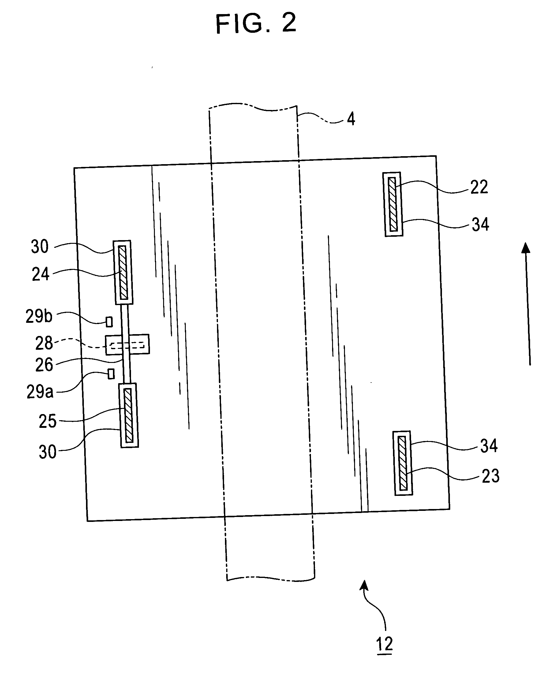
[0024] FIGS. 1 to 5 shows an overhead travelling carriage 2 according to the embodiment. In these figures, 4 is a running rail provided near, for example, a ceiling of a clean room. 6 is a running driving section that runs the overhead travelling carriage 2 along the running rail 4. The overhead travelling carriage 2 is supplied with electricity from the running rail 4 to communicate with a controller (not shown in the drawings) in the overhead travelling carriage 2. 8 is a lateral feeding section that moves an elevate and lower driving section 10, a platform 12, and a cassette 16 in a lateral direction with respect to a longitudinal direction of the running rail 4, and the cassette 16 is an example of a conveyed article. The elevate and lower driving section 10 elevates or lowers the platform 12 to deliver or receive the cassette 16 to or from, for example, a load port below the running rail, a temporary...


PUM


Abstract

A platform 12 is supported by four belts 22 to 25. Of the belts 22 to 25, a pair of belts 24, 25 is attached to a pivoting arm 26 so that the pivoting arm 26 is pivotable around a pivoting shaft 28. Pivoting of the pivoting arm 26 absorbs, for example, the difference in length between the belts 24, 25. The present invention makes it possible to simplify an elevate and lower driving mechanism of the platform 12 and to easily adjust the lengths of the belts 22 to 25. The present invention also makes it possible to prevent vibration during elevation or lowering and to allow the belts 22 to 25 to stand long use.

Description

FIELD OF THE INVENTION [0001] The present invention relates to an overhead travelling carriage, and in particular, to hanging of a platform of the overhead travelling carriage. BACKGROUND OF THE INVENTION [0002] An overhead travelling carriage is provided in a clean room or a common plant, warehouse, library, hospital, or the like. The overhead travelling carriage runs along a running rail provided near a ceiling of the building. The overhead travelling carriage conveys articles by elevating or lowering the platform. To elevate and lower the platform, it is possible to use hanging members such as belts, wires, or ropes to support three or four points on the platform. [0003] The Unexamined Japanese Patent Application Publication (Tokkai-Hei) No. 2003-118972 proposes an elevate and lower driving section 80 such as the one shown in FIG. 6, and a pair of drums 82 is installed along each of three sides of an equilateral triangle so that the hanging members can be wound around and fed fro...

Claims


Application Information

Patent Timeline
Patent Type & Authority Applications(United States)
IPC IPC(8): B66C19/00
CPCB66C13/06Y10S414/14H01L21/67733B66C17/00B66C17/04B66F7/02
Inventor NAKAO, TAKASHINAKAMURA, YOICHI
Owner MURATA MASCH LTD
Why Eureka
Try Eureka