Key switch and keyboard

a key switch and keyboard technology, applied in the direction of emergency actuators, contact mechanisms, electrical devices, etc., can solve the problems of data not being input by the keyboard, the key top is deflected, and the usability is worsened, so as to achieve the effect of lowering and elevating

Inactive Publication Date: 2018-03-29
FUJITSU COMPONENENT LTD
View PDF8 Cites 1 Cited by
  • Summary
  • Abstract
  • Description
  • Claims
  • Application Information

AI Technical Summary

Benefits of technology

[0008]According to an embodiment, there is provided a key switch including a key top; a pair of links that support the key top such that the key top is capable of being elevated and lowered; and a switch that opens and closes a contact point with respect to an elevating operation of the key top, wherein each of the links includes two arms, a connection portion that connects the two arms, two first shafts respectively formed at outer portions of the two arms, and two second shafts respectively formed at inner portions of the two arms, and wherein the key top includes at least four first support portions each being provided with a first guide groove in which the respective first shaft is slidable, and at least four second support portions each being provided with a second guide groove in which the respective second shaft is slidable.

Problems solved by technology

However, when the key top is thin, the key top is deflected when a corner of the key top is pressed.
Thus, the membrane switch may not be switched on even when the key top is pressed, data cannot be input by the keyboard, and usability is worsened.
However, if the key top is thick, the key switch becomes also thick, and it is impossible to satisfy the requirement of providing a thin keyboard.

Method used


Image

  • Key switch and keyboard
  • Key switch and keyboard
  • Key switch and keyboard

Examples


first embodiment

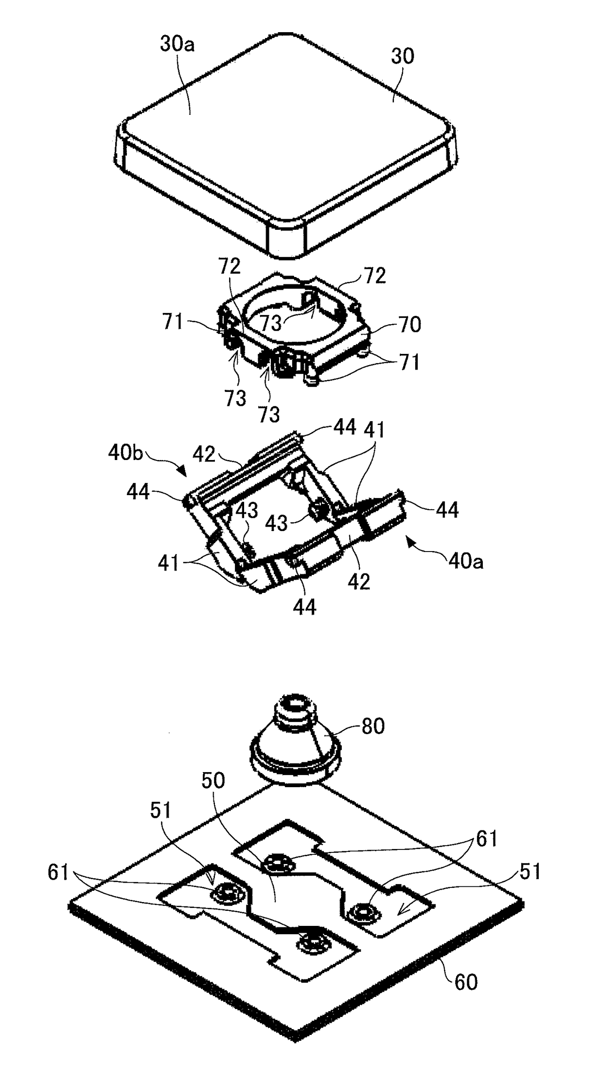
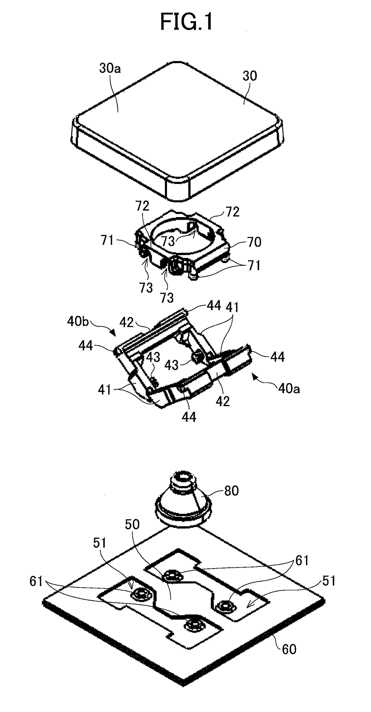
[0061]A key switch of a first embodiment is described. FIG. 5 is an exploded perspective view of the key switch of the embodiment. FIG. 6 is a perspective view illustrating an appearance of the key switch where a key top is removed.

[0062]As illustrated in FIG. 5, the key switch includes a key top 130, a pair of links 140a and 140b that cause an elevating operation of the key top 130 and a membrane switch 150 that switches on and off a contact point with an electric circuit in accordance with the elevating operation of the key top 130. The membrane switch 150 is provided on a support plate 160. The pair of links 140a and 140b are attached to the support plate 160 by a frame-shaped housing 170, and the membrane switch 150 is provided between the support plate 160 and the pair of links 140a and 140b.

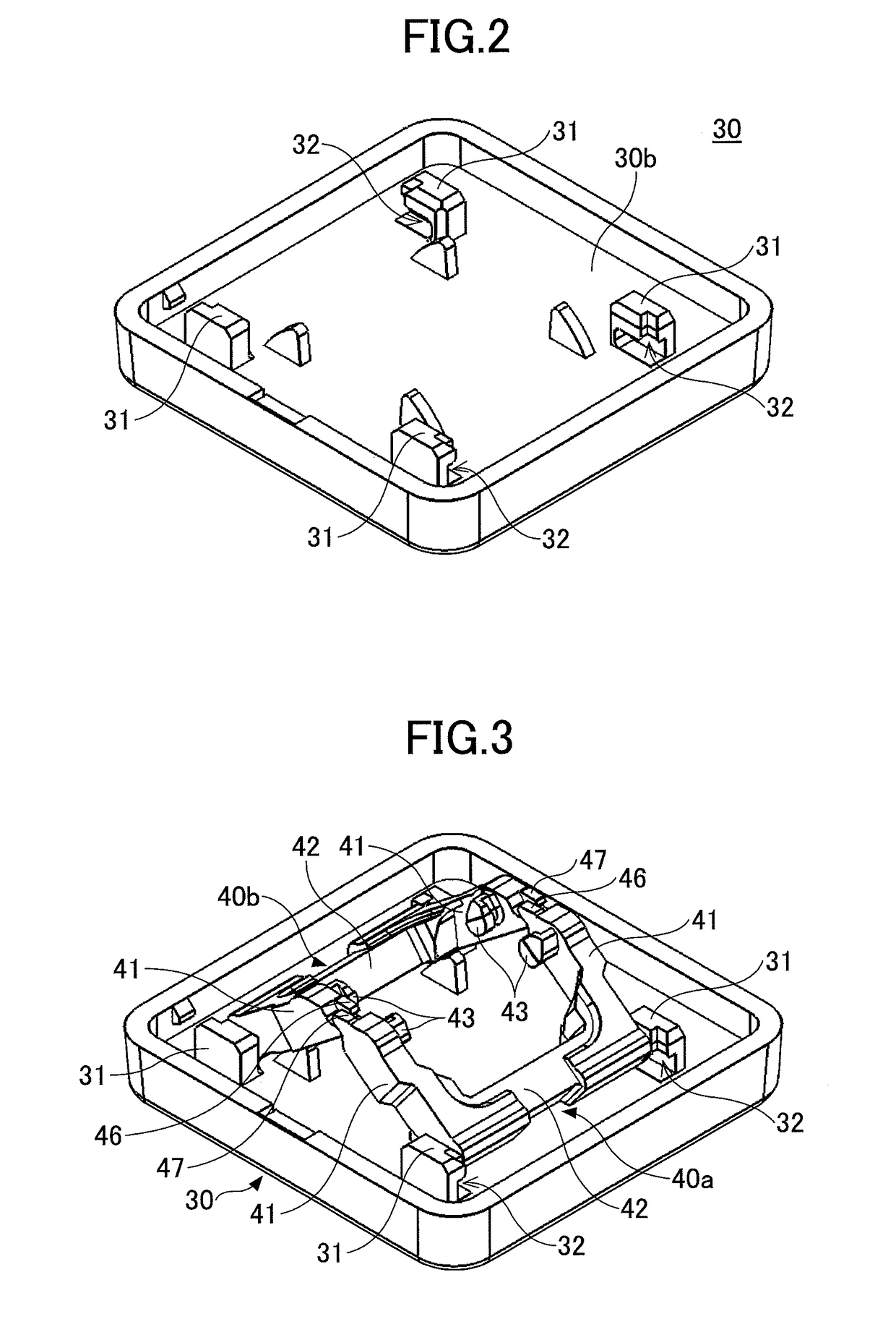
[0063]The key top 130 substantially has a rectangular shape in a planar view, and an upper surface 130a is an operation surface that is pressed and operated by a user. The housing 170 is a...

second embodiment

[0083]Second embodiment is described. FIG. 15 is a perspective view of a lower surface 130 of a key top 230 of the embodiment. FIG. 16 is a perspective view illustrating a state in which the pair of links 140a and 140b are attached to the key top 230. FIG. 17A is a view illustrating a state in which a center of the key top 230 is pressed, and FIG. 17B is a view illustrating a state in which an edge of the key top 230 is pressed. According to the second embodiment, instead of the two second support portions 132 of the key top 130 of the first embodiment, a second support portion 232 is provided for each of the links 140a and 140b. The second support portion 232 has a structure as if the two second support portions 132 of the key top 130 of the first embodiment are connected with each other.

[0084]The second support portions 232 are formed at the lower surface 130b of the key top 230. The second guide grooves 134 are provided at both sides of each of the second support portions 232, an...

third embodiment

[0086]Third embodiment is described. FIG. 18 is a perspective view of a lower surface 130b of a key top 330 of the embodiment. FIG. 19 is a perspective view illustrating a state in which the links 140a and 140b are attached to the key top 330. According to the third embodiment, instead of the two first support portions 131, provided at the same side for the links 140a and 140b, of the key top 130 of the first embodiment, a first support portion 331 is provided. The first support portion 331 has a structure as if the two first support portions 131 of the key top 130 of the first embodiment at the same side are connected with each other.

[0087]In the third embodiment, the first support portions 331 are formed at the lower surface 130b of the key top 330. The first support portion 331 is provided with the first guide grooves 133 at positions facing the respective second guide grooves 134. By forming such a first support portion 331, the thickness of the key top 330 at an area where the ...


PUM


Abstract

A key switch includes a key top; a pair of links that support the key top such that the key top is capable of being elevated and lowered; and a switch that opens and closes a contact point with respect to an elevating operation of the key top, wherein each of the links includes two arms, a connection portion that connects the two arms, two first shafts respectively formed at outer portions of the two arms, and two second shafts respectively formed at inner portions of the two arms, and wherein the key top includes at least four first support portions each being provided with a first guide groove in which the respective first shaft is slidable, and at least four second support portions each being provided with a second guide groove in which the respective second shaft is slidable.

Description

CROSS-REFERENCE TO RELATED APPLICATION[0001]The present application is based on and claims the benefit of priority of Japanese Priority Application No. 2016-189685 filed on Sep. 28, 2016, the entire contents of which are hereby incorporated by reference.BACKGROUND OF THE INVENTION1. Field of the Invention[0002]The present invention relates to a key switch and a keyboard.2. Description of the Related Art[0003]Small and thin electronic devices such as notebook personal computers are desired, and thus, a thin keyboard including a plurality of key switches is mounted on the electronic device. For example, a key switch of a gear link type includes a support plate, a key top, links provided between the support plate and the key top to cause an elevating operation of the key top, and a membrane switch that switches on and off a contact point of an electric circuit in accordance with the elevating operation of the key top. The links are attached on the support plate by a frame-shaped housin...

Claims


Application Information

Patent Timeline
Patent Type & Authority Applications(United States)
IPC IPC(8): H01H13/705
CPCH01H13/705H01H3/122H01H13/14H01H13/704H01H2215/006H01H2221/058H01H2233/012H01H2233/026H01H2233/03H01H2233/032H01H2233/046
Inventor KOSHIMURA, KATSUAKIKANEKO, MASAHIROYATSU, NOBUOKITAHARA, MIKITAKAHASHI, KOHEILIANG, CHUQI
Owner FUJITSU COMPONENENT LTD
Why Eureka
Try Eureka