Device connector

Active Publication Date: 2012-11-08
SUMITOMO WIRING SYST LTD
View PDF3 Cites 3 Cited by
  • Summary
  • Abstract
  • Description
  • Claims
  • Application Information

AI Technical Summary

Benefits of technology

[0014]The leading end of the flexible piece may be near a center of the case-side connector in forward and backward directions.

Problems solved by technology

However, a separate service cover then would be required for each opening, thereby making a mounting operation cumbersome.
However, the larger service cover is mor

Method used


Image

  • Device connector
  • Device connector
  • Device connector

Examples


Embodiment Construction

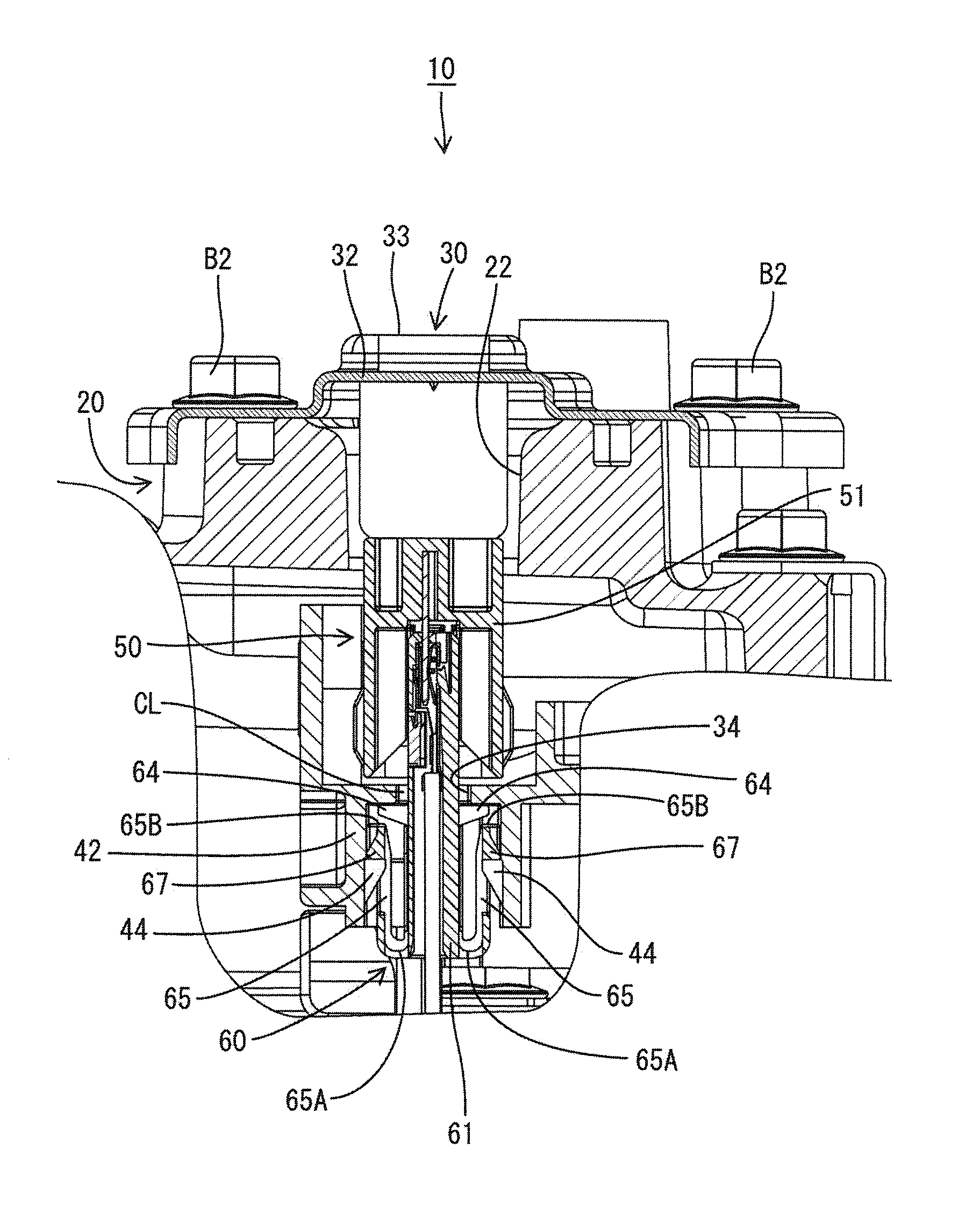
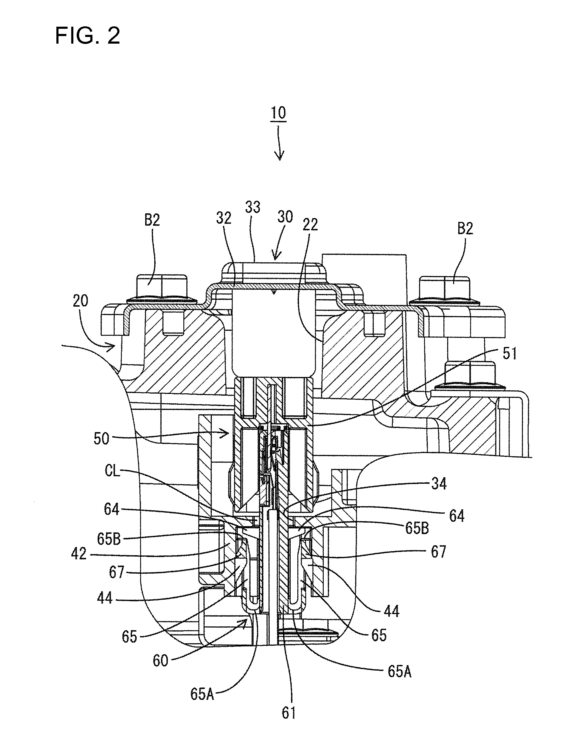
[0028]A device connector 10 of this embodiment has a connector connecting portion 21 connectable to a harness-side connector H / C at an end of a wiring harness W / H, as shown in FIG. 1. Only one connector connecting portion 21 is shown in FIG. 1, but the device connector 10 actually has plural connector connecting portions 21.

[0029]The device connector 10 has a metal case 20 and the connector connecting portion 21 extends through a side surface of the metal case 20. A terminal block 40 is arranged in the case 20 and a service hole 22 in the upper surface of this case 20 enables bolts of the terminal block 40 to be tightened. A service cover 30 is provided for closing the service hole 22 after the bolt tightening operation to seal the interior of the case 20.

[0030]As shown in FIG. 4, the harness-side connector H / C includes a harness-side terminal H / T crimped and connected to a core exposed by removing insulation coating at an end of the wiring harness W / H. The harness-side terminal H / T...


PUM


Abstract

A device connector (10) includes a service cover (30) to close a service hole (22) on a case (20). A case-side connector (60) is arranged in the case (20) and mounted in a mounting recess (42) in a terminal block (40). A cover-side connector (50) is provided integrally to the service cover (30) and is connected to the case-side connector (60) in a waiting state to form an interlock circuit when the service cover (30) is mounted on the case (20). Flexible pieces (65) hold the case-side connector (60) with a clearance (CL) between the case-side connector (60) and the inner wall of the mounting recess (42) when the case-side connector (60 is in the waiting state. On the other hand, the flexible pieces (65) bias the case-side connector (60) to return the case-side connector (60) to the waiting state when the clearance (CL) changes.

Description

BACKGROUND OF THE INVENTION[0001]1. Field of the Invention[0002]The invention relates to a device connector in a case of a device in a vehicle, the case being formed with an opening used to perform a bolt tightening operation for a terminal block in the case.[0003]2. Description of the Related Art[0004]U.S. Patent Application Publication No. 2010 / 0255728 discloses a device connector in a case of a device. A tightening tool is inserted through an opening in the case through to tighten bolts so that terminals of busbars or the like can be connected electrically conductively. A service cover is mounted on the case to close the opening after the bolt tightening operation is completed so that water, dust and the like do not enter the case through the opening.[0005]An interlock circuit switches an electrical circuit in the device to an OFF state as a safety measure when the service cover is removed from the case even though the terminals are in an electrically conductive state. Specifical...

Claims


Application Information

Patent Timeline
IPC IPC(8): H01R13/44
CPCH01R2201/26H01R13/6315
Inventor KAWAMURA, MASAYUKI
Owner SUMITOMO WIRING SYST LTD
Why Eureka
Try Eureka