Case for mobile communication device with flash and camera controls

a mobile communication device and control panel technology, applied in the field of cases for mobile communication devices with flash and camera controls, can solve the problems of detracting from the user's experience of using the mobile device camera, lack of gripping a mobile device, lack of traditional camera look and feel,

Active Publication Date: 2012-11-08
HALELUK ROBERT
View PDF11 Cites 127 Cited by
  • Summary
  • Abstract
  • Description
  • Claims
  • Application Information

AI Technical Summary

Benefits of technology

[0007]A battery compartment in the case holds at least one battery sufficient to drive the controller and flash device. The outer surface contour of the case is configured with or as a hand grip to provide the user with a “genuine” camera feel. Control actuators, preferably in the form of button actuators, control the shutter release and zoom controls (where available) in the mobile device camera. In flash mode, the case controller signals the camera (through the connection formed by the complementary connectors) to take a picture via the shutter control actuator to which the mobile's controller responds by sending a signal to the flash device back through the connector. In this way, the flash device and camera shutter may be synchronised so that the shutter does not open until the flash device is triggered.

Problems solved by technology

Such phones, however, often lack the look and feel of a traditional camera and therefore detract from a user's experience in using the mobile device camera.
In many cases, mobile phones are often smaller and have less of an ergonomic feel of a traditional camera, for example are very light weight and lack a means for gripping a mobile device in a way in which a traditional camera is known to be gripped while shooting pictures or video.
As mobile devices are intended to be light weight, and efficiently use electrical power stored in batteries built into the mobile device, the mobile devices are not known to include flash devices to provide a flash of light to enhance picture quality, where necessary, due to the need for relative large amounts of electrical power to drive such flash devices.

Method used


Image

  • Case for mobile communication device with flash and camera controls
  • Case for mobile communication device with flash and camera controls
  • Case for mobile communication device with flash and camera controls

Examples


Embodiment Construction

[0027]The following is a detailed description of example embodiments of the invention depicted in the accompanying drawings. The example embodiments are in such detail as to clearly communicate the invention and are designed to make such embodiments obvious to a person of ordinary skill in the art. However, the amount of detail offered is not intended to limit the anticipated variations of embodiments; on the contrary, the intention is to cover all modifications, equivalents, and alternatives falling within the spirit and scope of the present invention, as defined by the appended claims.

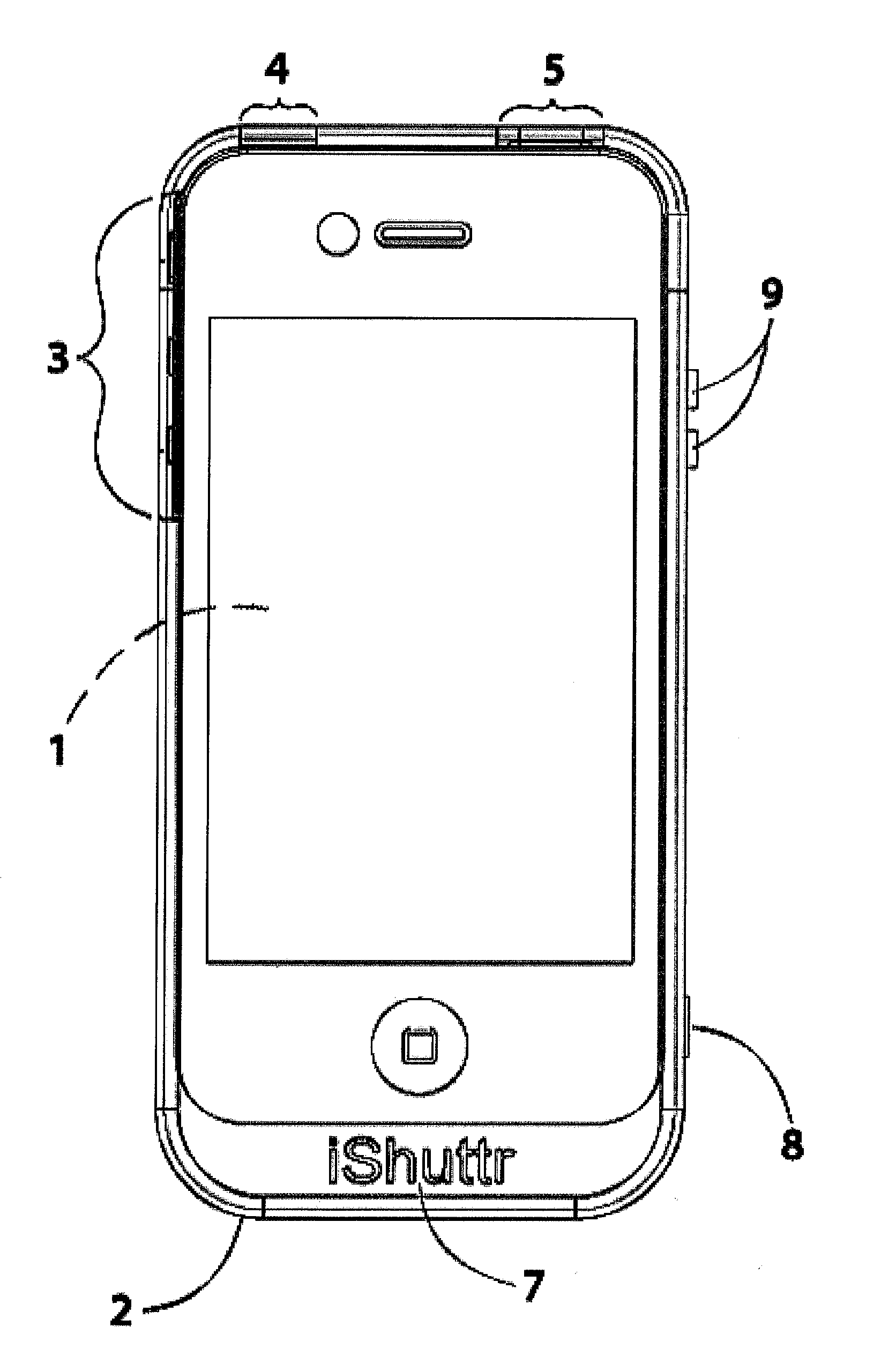
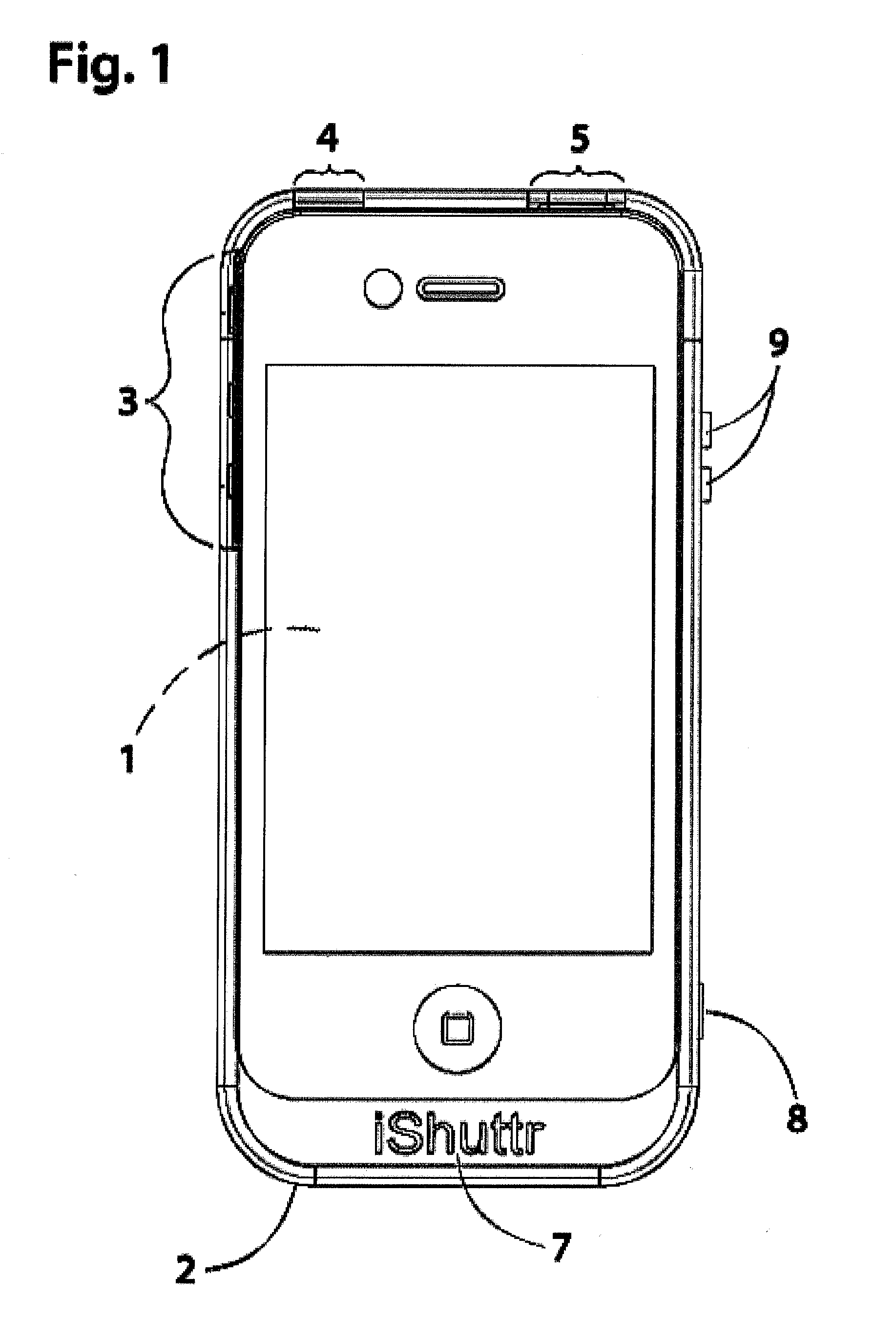
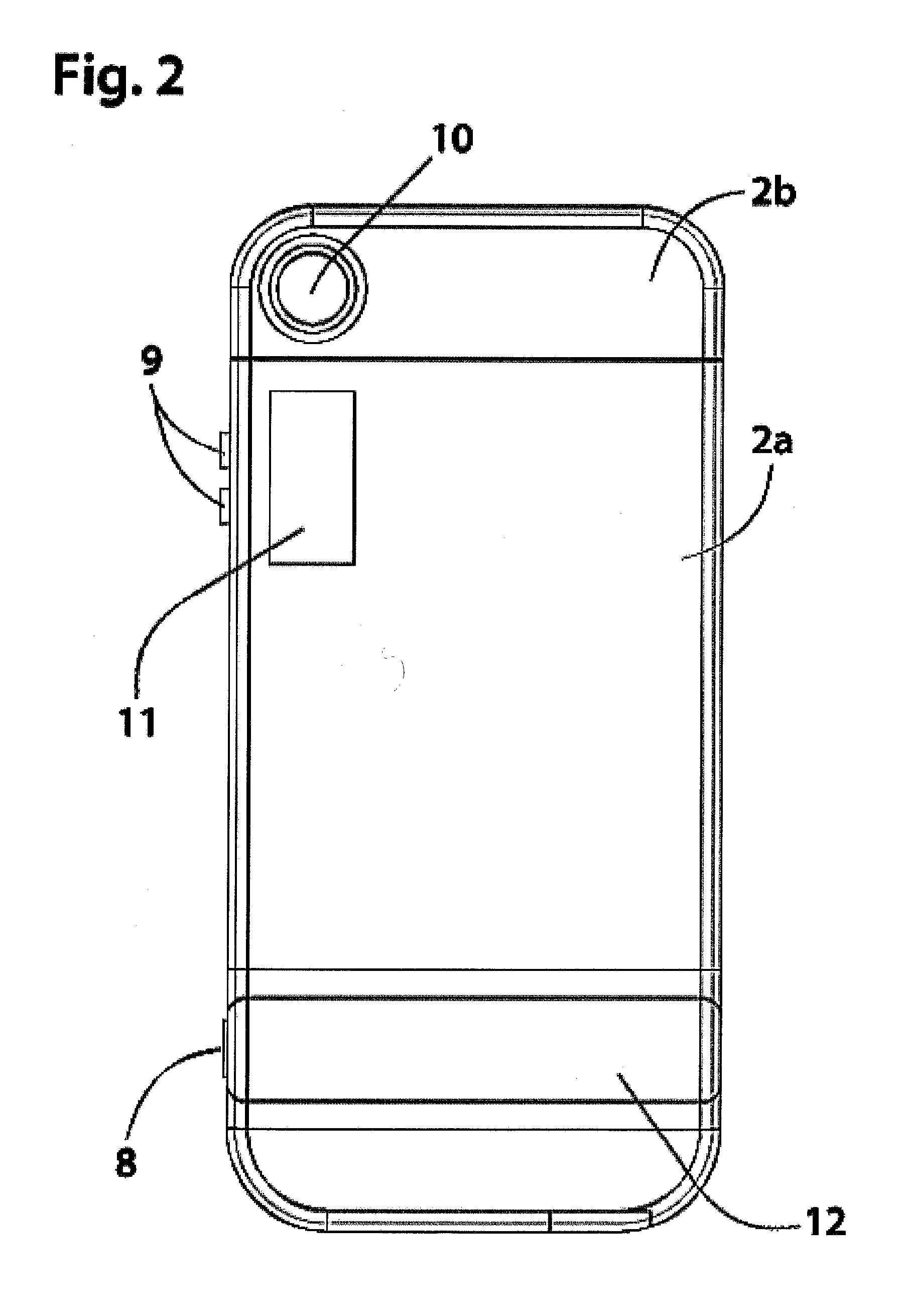
[0028]The inventive case essentially turns a mobile device into a camera, with the look, feel, contour and operation of conventional point and shoot cameras.

[0029]FIGS. 1-11 depict the inventive case configured for use with an iPhone™. The embodiment configured for use with an iPhone™ is depicted for explanation purposes only, where the inventive case may be modified where necessary to accommodate an...


PUM


Abstract

A mobile device case is formed with a hollow case housing for receiving a mobile device and controlling a mobile device camera therein. The mobile device includes a case connector for electronically connecting the case to the mobile device at insertion of the mobile device into the hollow case housing and at least one camera control actuator for controlling operation of the mobile device camera, when the mobile device is present in the hollow case housing. The hollow case housing comprises a first housing section and a second housing section that comes together by respective tongue and groove elements to thereby encapsulate the mobile device.

Description

CROSS-REFERENCE TO RELATED APPLICATIONS[0001]This application claims priority under 35 U.S.C. §119 from U.S. Provisional Patent Document No. 61 / 482,987, filed May 5, 2011, all of the contents of which are incorporated by reference herein.BACKGROUND OF THE INVENTION[0002]The present invention relates broadly to a case constructed to receive a mobile communication device (or mobile device) that includes a flash strobe and controls for controlling a camera within the mobile device in order to provide the case user with an experience of a point and shoot camera.[0003]Known mobile devices include cameras for enhancing the experience of the mobile device user. Such phones, however, often lack the look and feel of a traditional camera and therefore detract from a user's experience in using the mobile device camera. In many cases, mobile phones are often smaller and have less of an ergonomic feel of a traditional camera, for example are very light weight and lack a means for gripping a mobi...

Claims


Application Information

Patent Timeline
Patent Type & Authority Applications(United States)
IPC IPC(8): H04W88/02
CPCH04B1/3888H04M1/72527H04M1/0202H04M1/724092
Inventor HALELUK, ROBERT
Owner HALELUK ROBERT
Why Eureka
Try Eureka