Method for operating a transmission device having a plurality of friction-fit shift elements and at least one form-fit shift element

a transmission device and shift element technology, applied in mechanical devices, transportation and packaging, gearing, etc., can solve the problems of insufficient efficiency of transmission devices and inability to disengage form-locking shift elements within, and achieve high shift comfort

Active Publication Date: 2012-11-08
ZF FRIEDRICHSHAFEN AG
View PDF1 Cites 22 Cited by
  • Summary
  • Abstract
  • Description
  • Claims
  • Application Information

AI Technical Summary

Benefits of technology

[0007]Therefore, the problem addressed by the present invention is to provide a method for operating a transmission device by means of which shifts in transmission devices, in which

Problems solved by technology

Since, in a manner known per se, such transmission devices can only be operated with insufficient degrees of efficiency because of drag losses that occur in the area of disengaged frictionally engaging shift elements, certain frictionally engaging shift elements are replaced by form-locking shift elements.
Disadvantageously, depending on the design arrangement of the shift elements, while performing a request for a change of operating state of the transmission

Method used


Image

  • Method for operating a transmission device having a plurality of friction-fit shift elements and at least one form-fit shift element
  • Method for operating a transmission device having a plurality of friction-fit shift elements and at least one form-fit shift element
  • Method for operating a transmission device having a plurality of friction-fit shift elements and at least one form-fit shift element

Examples


Embodiment Construction

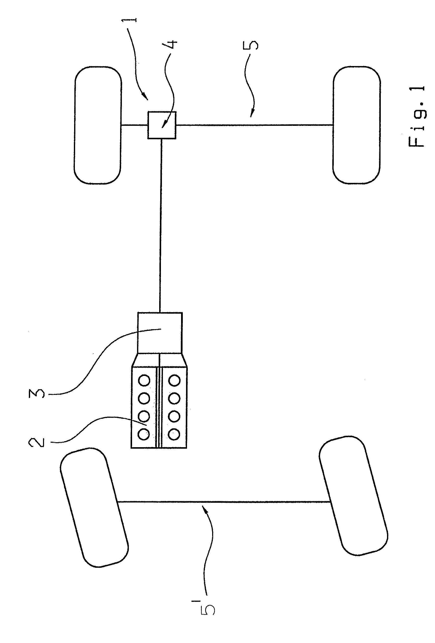
[0023]FIG. 1 shows a vehicle drive train 1 having a drive machine 2 designed here as an internal combustion engine, having a transmission device 3, by means of which different transmission ratios for forward and reverse travel can be represented, having a differential unit 4 and having two vehicle axles 5, 5′, wherein here the vehicle axle 5 is the rear vehicle axle and the vehicle axle 5′ is the front vehicle axle.

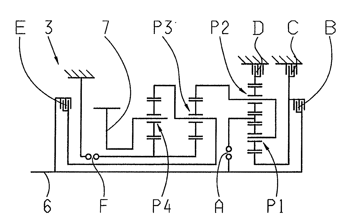
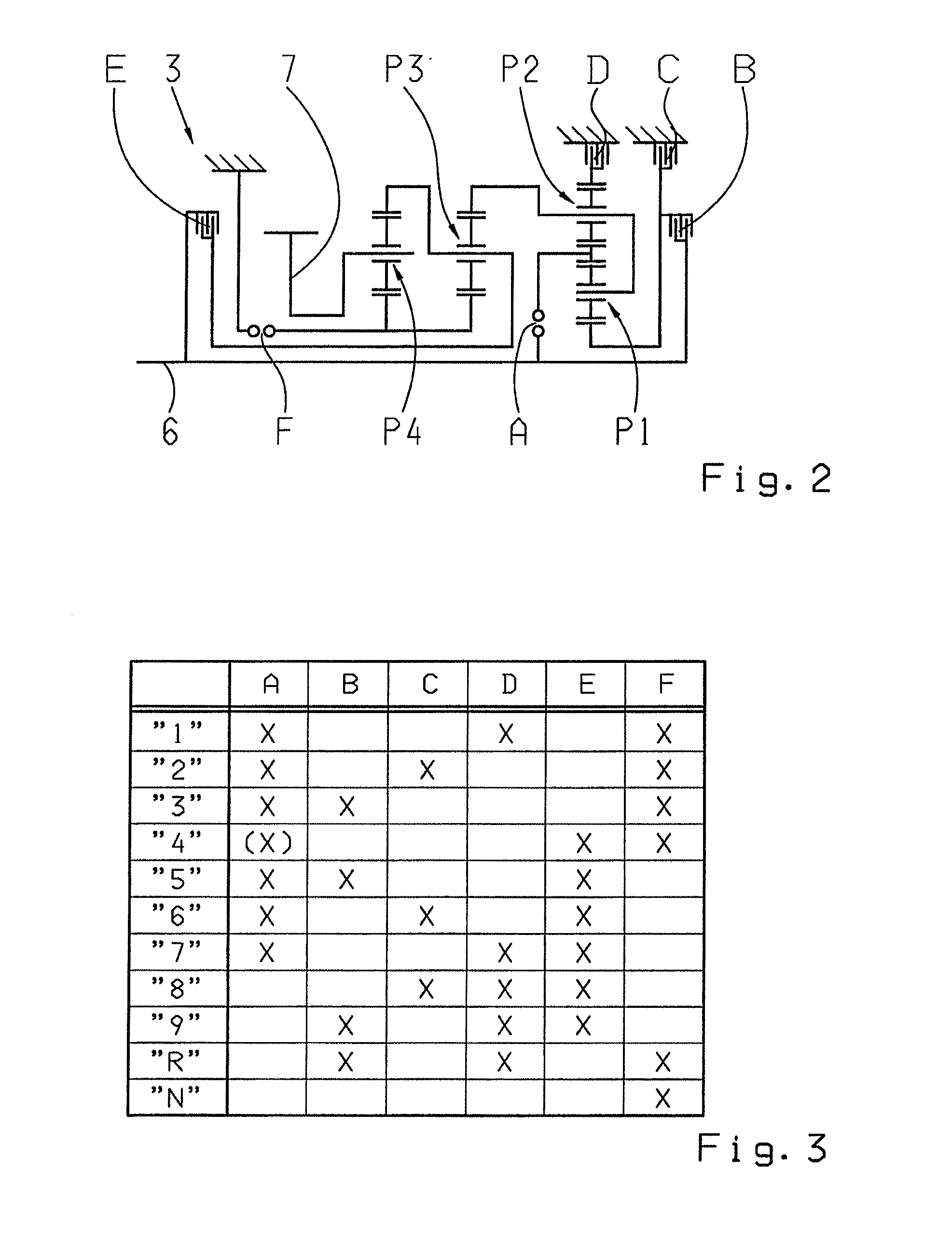
[0024]A gear diagram of the transmission device 3, or a multi-stage transmission, is shown in FIG. 2, which is known in principle from the generic document DE 10 2008 000 429.4 from the applicant. The transmission device 3 comprises a transmission input shaft 6 and a transmission output shaft 7, which is connected to the differential unit 4 when installed in a vehicle, while the transmission input shaft 6 is operatively connected to the drive machine 2.

[0025]Furthermore, the transmission device 3 comprises four planetary gear sets P1 to P4, wherein the first and the secon...


PUM


Abstract

A method of operating a transmission device (3) having a plurality of frictionally engaging shift elements (B, C, D and E) and at least one form-locking shift element (A, F) for implementing different transmission ratios. Upon a requested change in operating state of the transmission device (3), the at least one form-locking shift element (A) is transferred into an at least nearly load-free state, during which the form-locking shift element (A) is transferred from an engaged to a disengaged operating state by increasing the transfer capability of at least one frictionally engaging shift element (E), which is not engaged in the power flow of the transmission device (3) either to represent the present operating state or to represent the requested operating state.

Description

[0001]This application is a National Stage completion of PCT / EP2010 / 070385 filed Dec. 21, 2010, which claims priority from German patent application serial no. 10 2010 000 859.1 filed Jan. 13, 2010.FIELD OF THE INVENTION[0002]The invention relates to a method for operating a transmission device having a plurality of frictionally engaging shift elements and at least one form-locking shift element.BACKGROUND OF THE INVENTION[0003]Vehicle drive trains known from the prior art are typically designed having an internal combustion engine and at least one transmission device, disposed between the internal combustion engine and an output drive, by means of which the transmission ratios that are required depending on the operating state can be provided.[0004]Such transmission devices known per se and implemented as automatic transmissions, are designed having shift elements for implementing different transmission ratios, by means of which a present torque can be transferred in a frictionally...

Claims


Application Information

Patent Timeline
IPC IPC(8): F16H3/62
CPCF16H3/666Y10T477/78F16H61/686F16H2003/442F16H2061/0407F16H2061/0429F16H2061/0481F16H2200/0065F16H2200/2012F16H2200/2046F16H2200/2064F16H2306/44F16H2306/46F16H2200/2094Y10T477/638F16H61/04
Inventor HERBETH, VALENTINEARNOLD, JORGMIHATSCH, GEORGSCHIMDT, ANDREASSCHMIDT, THILODIOSI, GABORMARGRAF, CHRISTOPH
Owner ZF FRIEDRICHSHAFEN AG
Why Eureka
Try Eureka