Multiple loop device for passing suture tails through a surgical pledget

a multi-loop device and surgical technology, applied in the field of surgical suturing, can solve the problems of inconvenient and reliable operation, increased needle injury and infection risk, and present inconvenient challenges and unnecessary risks, and achieve the effect of convenient grasping

Active Publication Date: 2012-11-08
LSI SOLUTIONS
View PDF4 Cites 48 Cited by
  • Summary
  • Abstract
  • Description
  • Claims
  • Application Information

AI Technical Summary

Benefits of technology

[0017]In accordance with still another aspect of the invention, the handle is curved to make it easier to grasp.

Problems solved by technology

While a pledget could be placed under the suture and above the tissue without the suture traversing through the pledget, this is often not practical or reliable under certain surgical conditions, especially those involving the remote suturing as are needed in many minimally invasive surgical procedures.
The use of pledgets with surgical suturing confers many compelling advantages, but placement of a pledget on the suture ends at the knot side of the suture still presents inconvenient challenges and unnecessary risks.
Prior to this invention, the requisite use of needles to pass suture through pledgets would require several extra steps, increase the risk of needle injury and infection, and may not prove possible in many modern surgical interventions.
Hand threading suture ends through tiny holes in pledgets is not practical and may not even be achievable in the diminished ambient light conditions of many video intensive operating rooms.
Custom slotted pledgets can offer some benefits, but may not satisfy the requirements for ease-of-use, effectiveness and safety in minimally invasive surgery applications, especially those involving automated suturing or automated knot placement technologies.
The currently marketed single loop wire snare devices now available for pulling suture through mechanical knots do not aid in the placement of suture through pledgets.

Method used


Image

  • Multiple loop device for passing suture tails through a surgical pledget
  • Multiple loop device for passing suture tails through a surgical pledget
  • Multiple loop device for passing suture tails through a surgical pledget

Examples


Embodiment Construction

[0044]Referring to FIGS. 1 and 2, a presently preferred embodiment of the invention is disclosed.

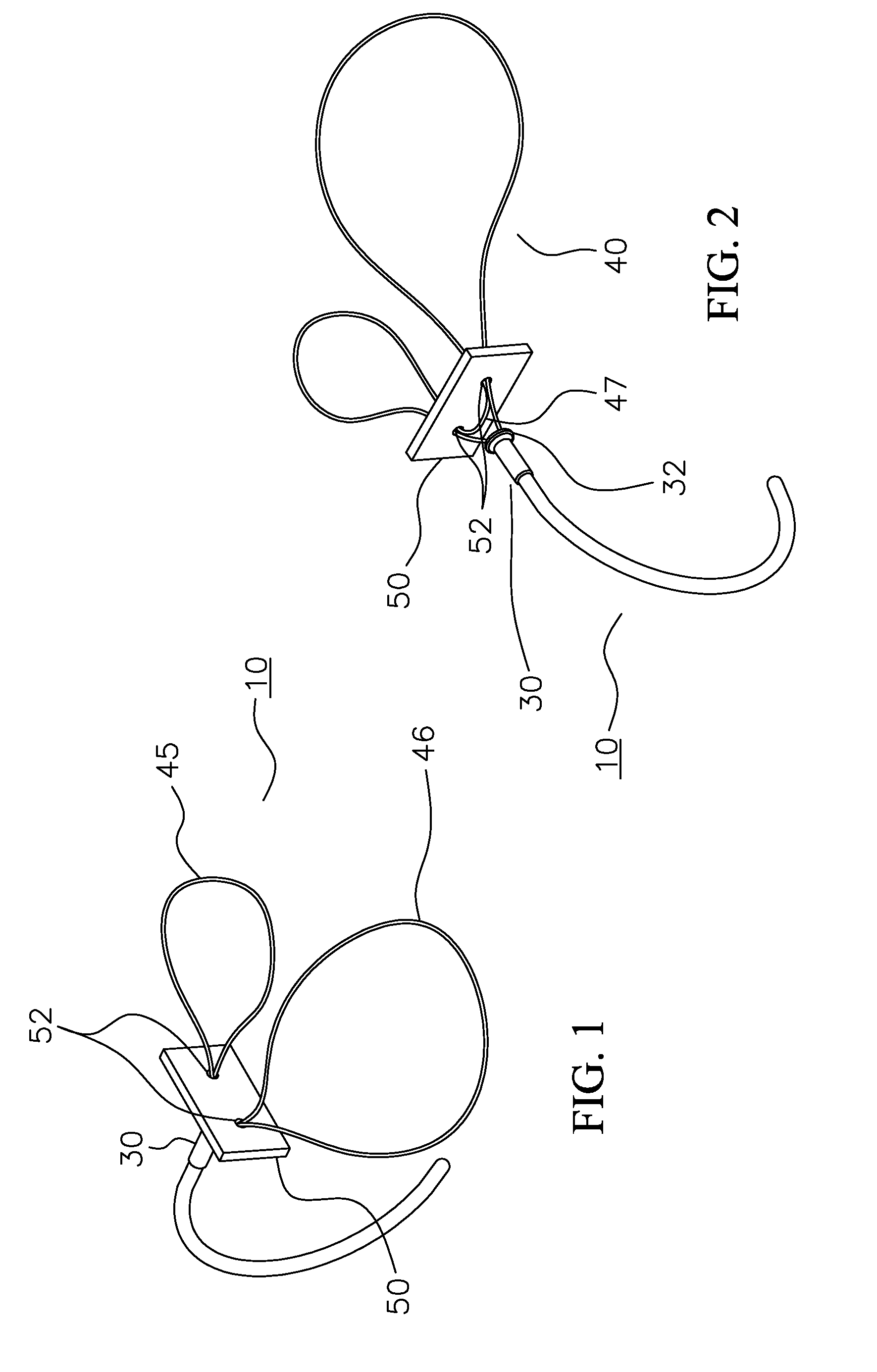
[0045]FIG. 1 shows a distal view of a dual snare pledget assembly 10 as presented for use. A large loop 46 and a small loop 45 having passed through and expanded outside of suture holes 52 formed in a pledget 50 in a fashion that allows for the positioning of the pledget 50 in proximity to a suture securing sleeve 30. While FIGS. 1-17 illustrate embodiments of the invention in which the large and small loops are formed from a single length of material, the loops may be formed separately as shown in FIG. 18.

[0046]FIG. 2 shows a proximal perspective view of the dual snare pledget assembly 10 of FIG. 1 relative to its intended field of use with the pledget 50 in position close to a head 32 of the suture securing sleeve 30. A folding loop 47 of a wire snare 40 transits the two suture holes 52 of the pledget 50.

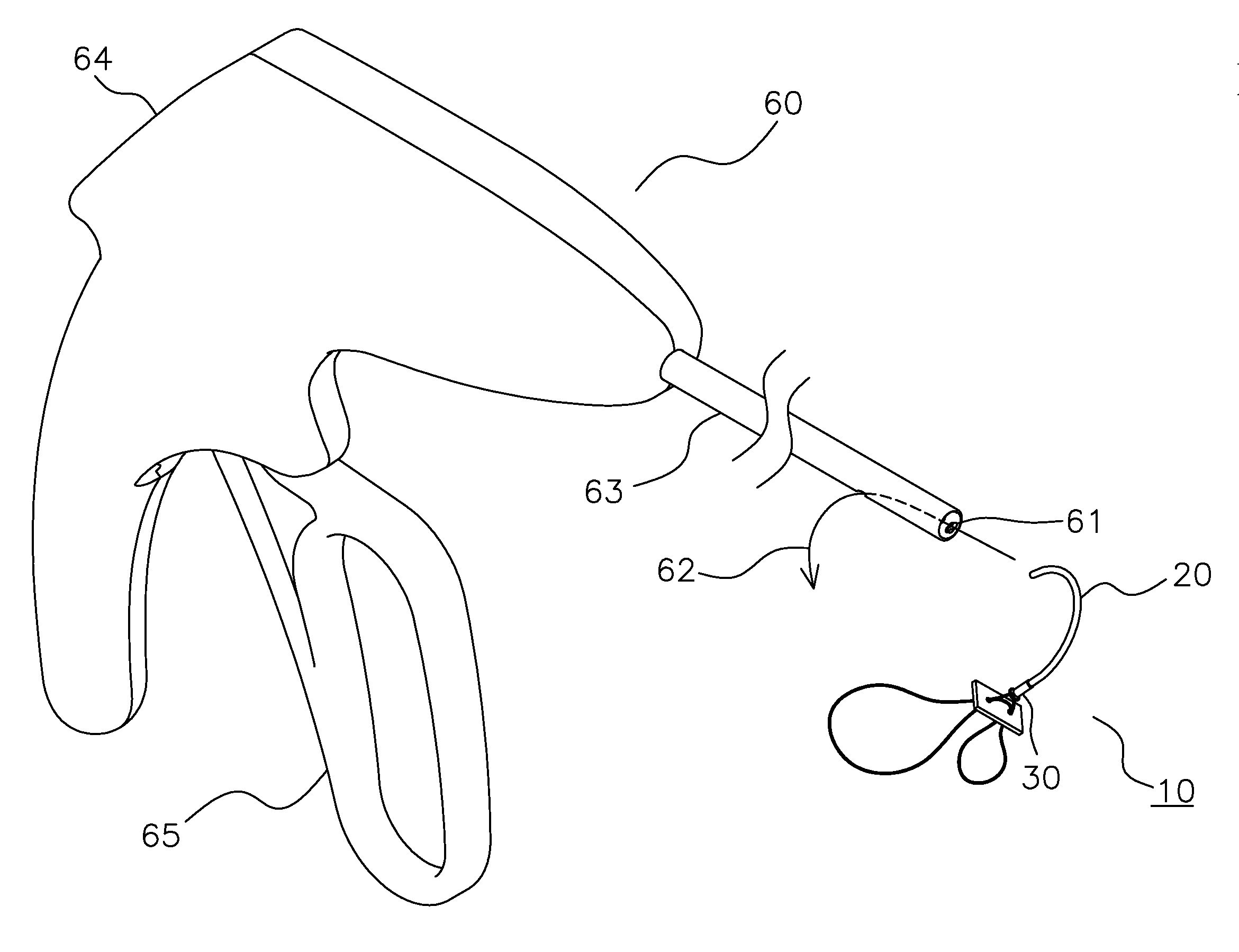
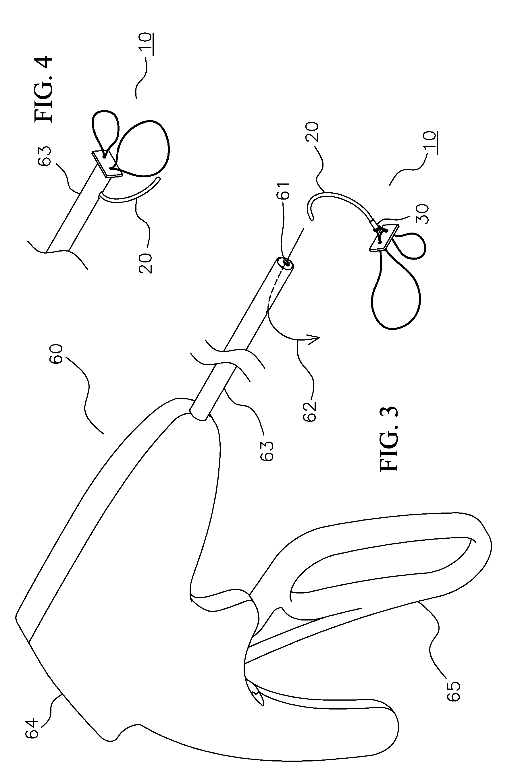
[0047]FIG. 3 is a perspective view of the dual snare pledget assembly 10 with its ...


PUM


Abstract

A surgical pledget assembly includes a pledget body having first and second apertures extending through the body, one or more snares passing through the apertures in the pledget body and including first and second suture engaging loops disposed on a distal side of the pledget, an optional third folding loop disposed on a proximal side of the pledget, and a handle secured to the ends of the snare or snares proximal to the pledget.

Description

CROSS-REFERENCE TO RELATED APPLICATIONS[0001]NoneBACKGROUND OF THE INVENTION[0002]This invention relates generally to surgical suturing and more particularly to a device for remotely placing a surgical pledget at a suturing site and drawing suture tails through the pledget to be secured proximally of the pledget.DESCRIPTION OF RELATED ART[0003]The general medical definition of a pledget is a small compress, tuft, or flat mass usually made of gauze or absorbent cotton that is laid over a wound or into a cavity to apply medication, exclude air, retain dressings or absorb discharged matter. The pledget concept, in a more specifically surgical application, often applies to material or bolster used to help reduce the risk of suture pulling through tissue that it is holding by cushioning and spreading the load of the suture against the underlying tissue. Surgical pledgets have been used throughout history and remain a routinely utilized adjunct to suture mediated tissue repair even in the...

Claims


Application Information

Patent Timeline
Patent Type & Authority Applications(United States)
IPC IPC(8): A61B17/04
CPCA61B17/0401A61B17/0485A61B17/0487A61B2017/0488A61B2017/0406A61B2017/0409A61B2017/00526A61B2017/0464F04C2270/041
Inventor SAUER, JUDE S.
Owner LSI SOLUTIONS
Why Eureka
Try Eureka