
System and method for planning and/or producing a dental prosthesis

Active Publication Date: 2012-11-08
NOBEL BIOCARE SERVICES AG
View PDF21 Cites 24 Cited by
  • Summary
  • Abstract
  • Description
  • Claims
  • Application Information

AI Technical Summary

Benefits of technology

[0017]Thus, when digitized, envelope data can be provided based on the envelope guide. The envelope data can provide guidance for the virtual planning of a dental prosthesis in relation to the desired result when the prosthesis is installed in the oral cavity of the patient.
[0038]Certain embodiments can eliminate the need to consider or provide separate smile data, e.g., from a photography, which may be a procedure prone to errors.

Problems solved by technology

For instance, it can be very time consuming, e.g., because the wax appliance may need to be sent back to the dental technician when the dentist has finished the patient specific adaptation.
Furthermore, the precision of the final restoration may suffer.
Many manual steps are a source of precision error, not at least due to the human factor.
Consequences may be dire for the patient.
Moreover, the range of possible products prepared by the dental technician may be limited.
In addition, flexibility concerning adaptation and verification of dental restorations may be limited.
Known computer based methods, such as disclosed in U.S. Pat. No. 6,814,575 ('575), may still require such time consuming manual work.
Hence, the method disclosed in '575 is limited by fixed positions of the manually prepared denture.
This computer based method thus lacks flexibility as it does not allow for a change of the teeth setup once the dental prosthesis is prepared, e.g., for taking into consideration a desired outcome of a dental restoration.
Moreover, no data is provided to the technician manually preparing the denture, which is related to an appearance or position of facial tissue when the denture is placed over the gum.
Thus, the final dental restoration, partly based on the denture, may not be optimal for the patient in terms of fit or aesthetics.
This was not possible hitherto, e.g., as erroneous excessive carving from a wax-up appliance meant that the appliance had to be discarded and a new appliance had to be manually created in a time consuming manner.

Method used


Image

  • System and method for planning and/or producing a dental prosthesis
  • System and method for planning and/or producing a dental prosthesis
  • System and method for planning and/or producing a dental prosthesis

Examples


Embodiment Construction

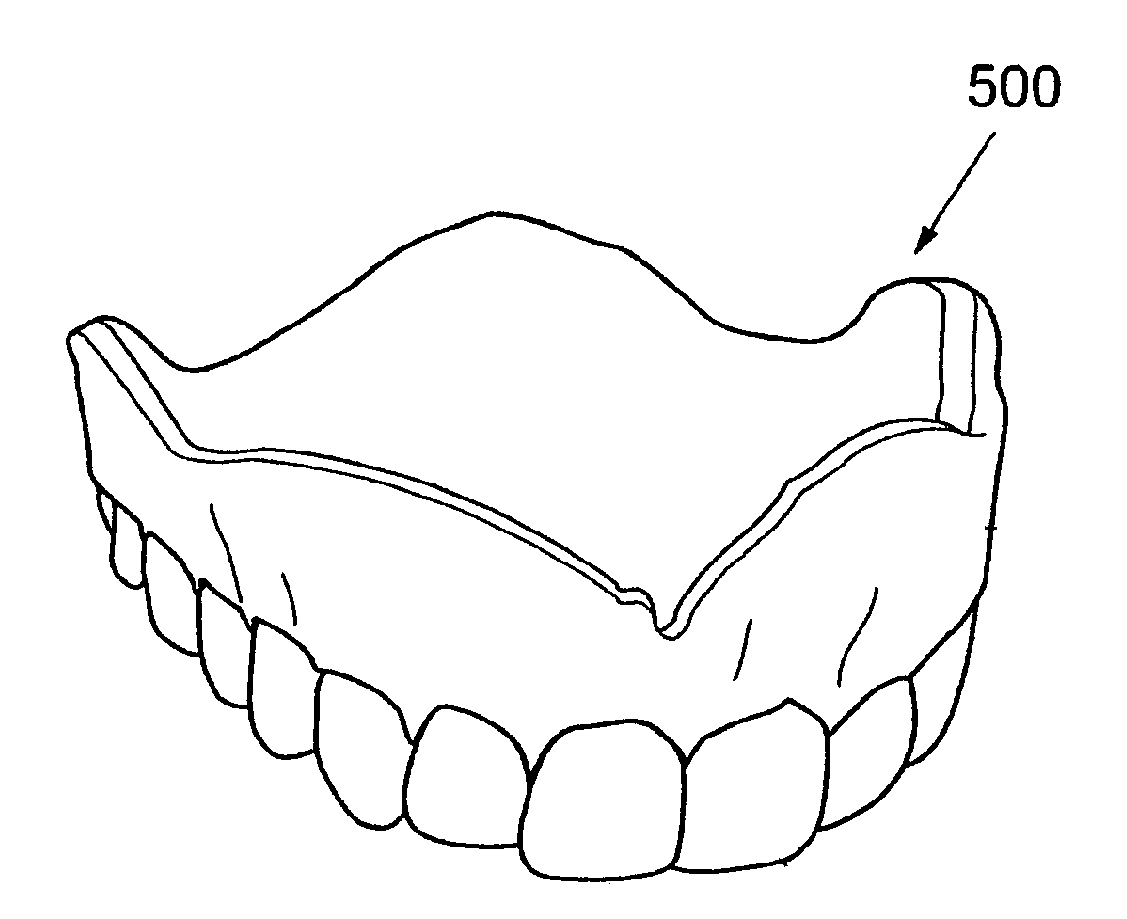
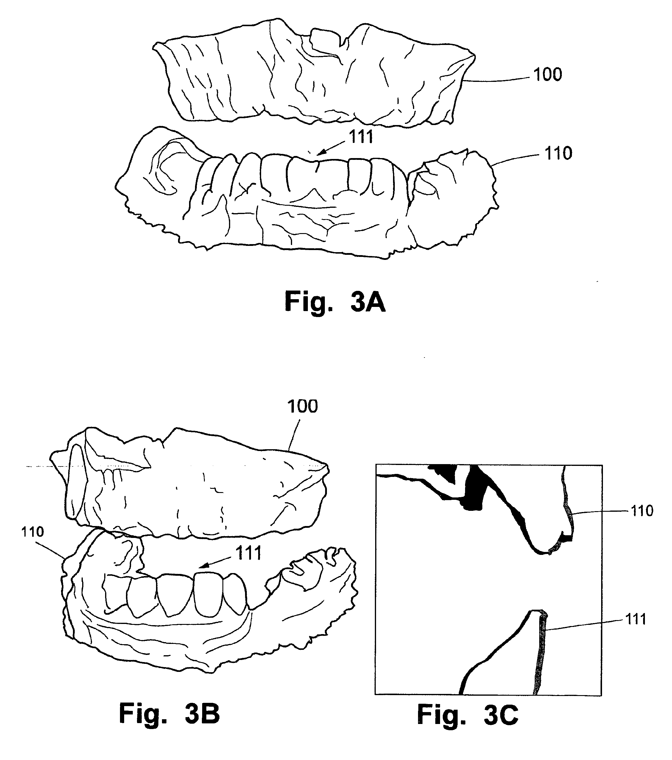
[0060]Specific embodiments will now be described with reference to the accompanying drawings. This invention may, however, be embodied in many different forms and should not be construed as limited to the embodiments set forth herein; rather, these embodiments are provided so that this disclosure will be thorough and complete, and will fully convey the scope to those skilled in the art. The terminology used in the detailed description of the embodiments illustrated in the accompanying drawings is not intended to be limiting. In the drawings, like numbers refer to like elements. The envelope guide is shown transparent or unshaded in some of the figures for illustrative purposes only.

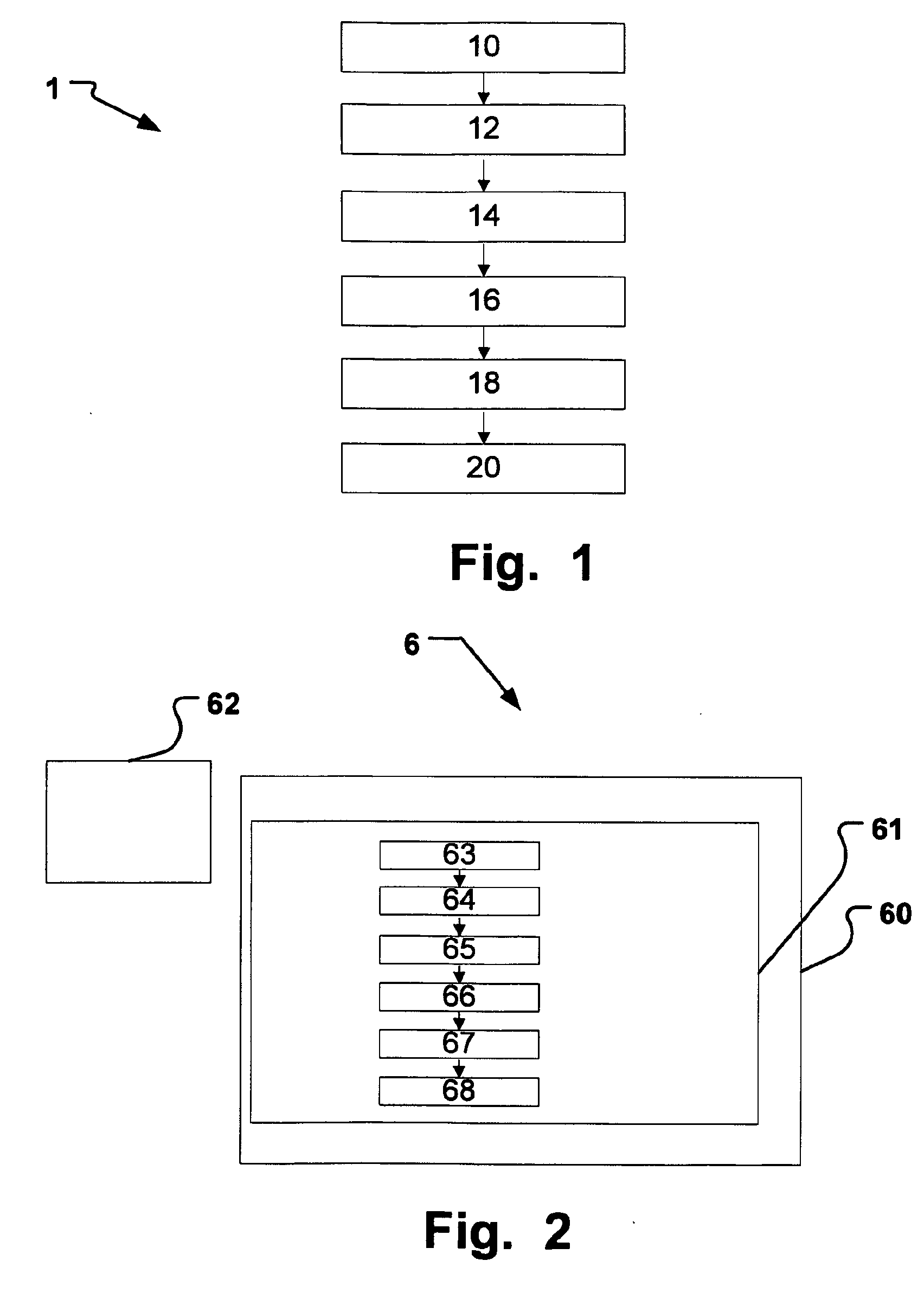
[0061]FIG. 1 is an example flowchart of a method 1 of virtually planning a dental prosthesis. The method 1 may also comprise planning of a dental restorative procedure including installation of the dental prosthesis planned using the method. The dental prosthesis may be installed in a real dental restorat...


PUM


Abstract

A method, system and computer program of planning a dental prosthesis in a patient are disclosed, including steps, units or code segments for virtually planning a dental prosthesis. Envelope data is provided of an envelope guide, including data corresponding to a support surface for facial tissue, which is desired to result when the dental prosthesis is installed in the oral cavity of the patient. An outer envelope of a desired dental prosthesis in the oral cavity is simulated based on the envelope data. A desired dental restoration is provided and adjusted in a virtual environment relative to the simulated outer envelope, and dental prosthesis data is generated based on the adjusted desired dental restoration usable for producing the dental prosthesis.

Description

CROSS-REFERENCE TO RELATED APPLICATIONS[0001]This application is a national stage application under 35 U.S.C.§371 of PCT Application No. PCT / EP2010 / 006929, filed on Nov. 15, 2010, which published in English as WO 2011 / 057810 on May 19, 2011, and which claims priority benefit of European Patent Application No. 09014296.9, filed on Nov. 16, 2009, the entire contents of which applications and publication are herein incorporated by reference in their entirety.BACKGROUND[0002]1. Field[0003]This invention pertains in general to the field of digital dental design. More particularly the application relates to computer based virtual planning of dental restorations comprising dental prosthesis, as well as for methods of providing components for the dental restoration including a dental prosthesis, or components related to the dental prosthesis to be used during a dental restorative procedure, based on production data which is based on the virtual planning.[0004]2. Description of the Related A...

Claims


Application Information

Patent Timeline
IPC IPC(8): A61C13/00G06F17/50
CPCA61C8/0095A61C13/08A61C13/0004
Inventor NILSSON, URBAN
Owner NOBEL BIOCARE SERVICES AG
Learn More