
Touch interface device having an electrostatic multitouch surface and method for controlling the device

a multi-touch surface, electrostatic technology, applied in the direction of instruments, computing, electric digital data processing, etc., can solve the problems of inability to individually control the haptic effects provided to each fingertip (e.g., different from each other) at the same time, and mechanical vibration may not support multi-touch

Active Publication Date: 2012-11-15
NORTHWESTERN UNIV
View PDF9 Cites 117 Cited by
  • Summary
  • Abstract
  • Description
  • Claims
  • Application Information

AI Technical Summary

Benefits of technology

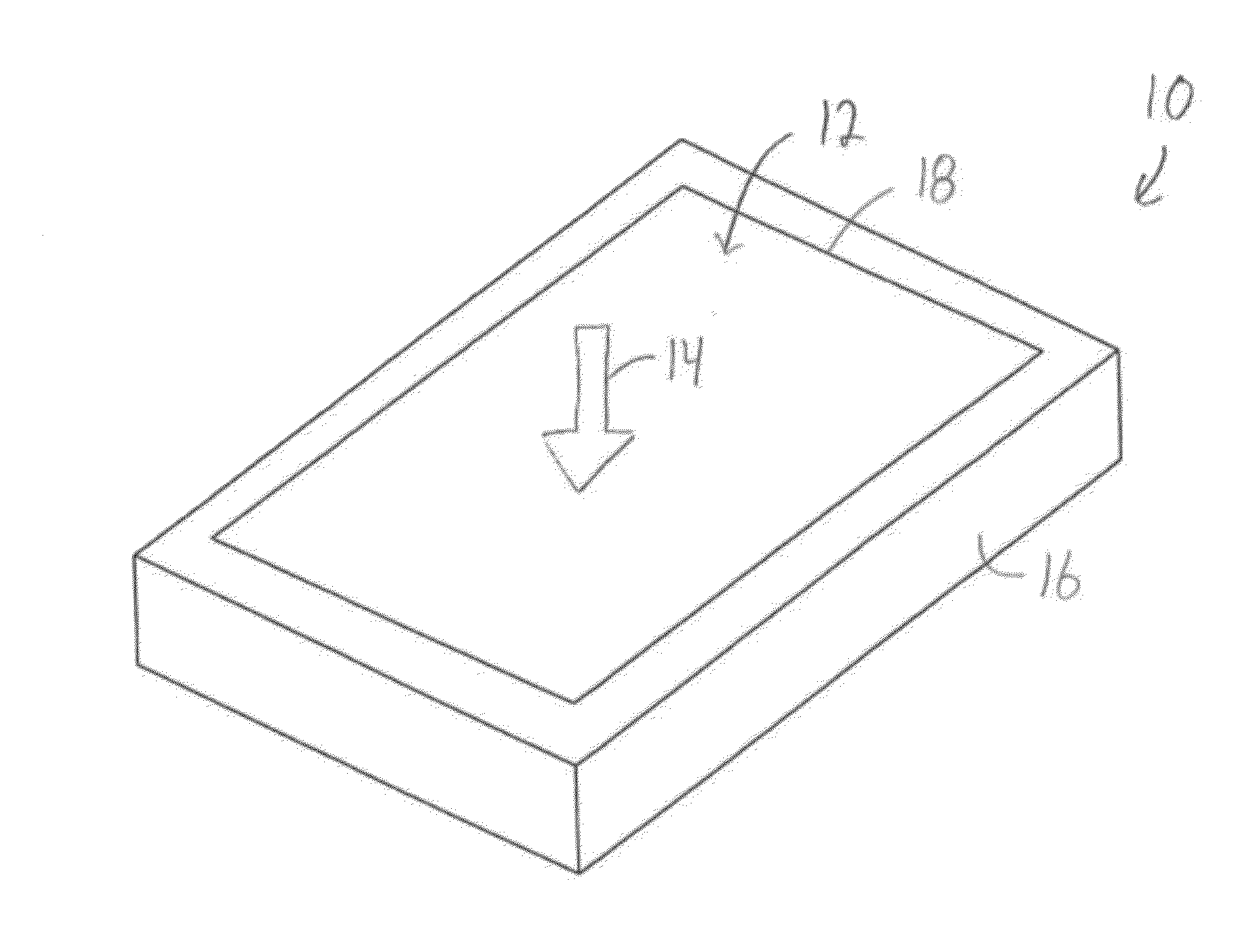
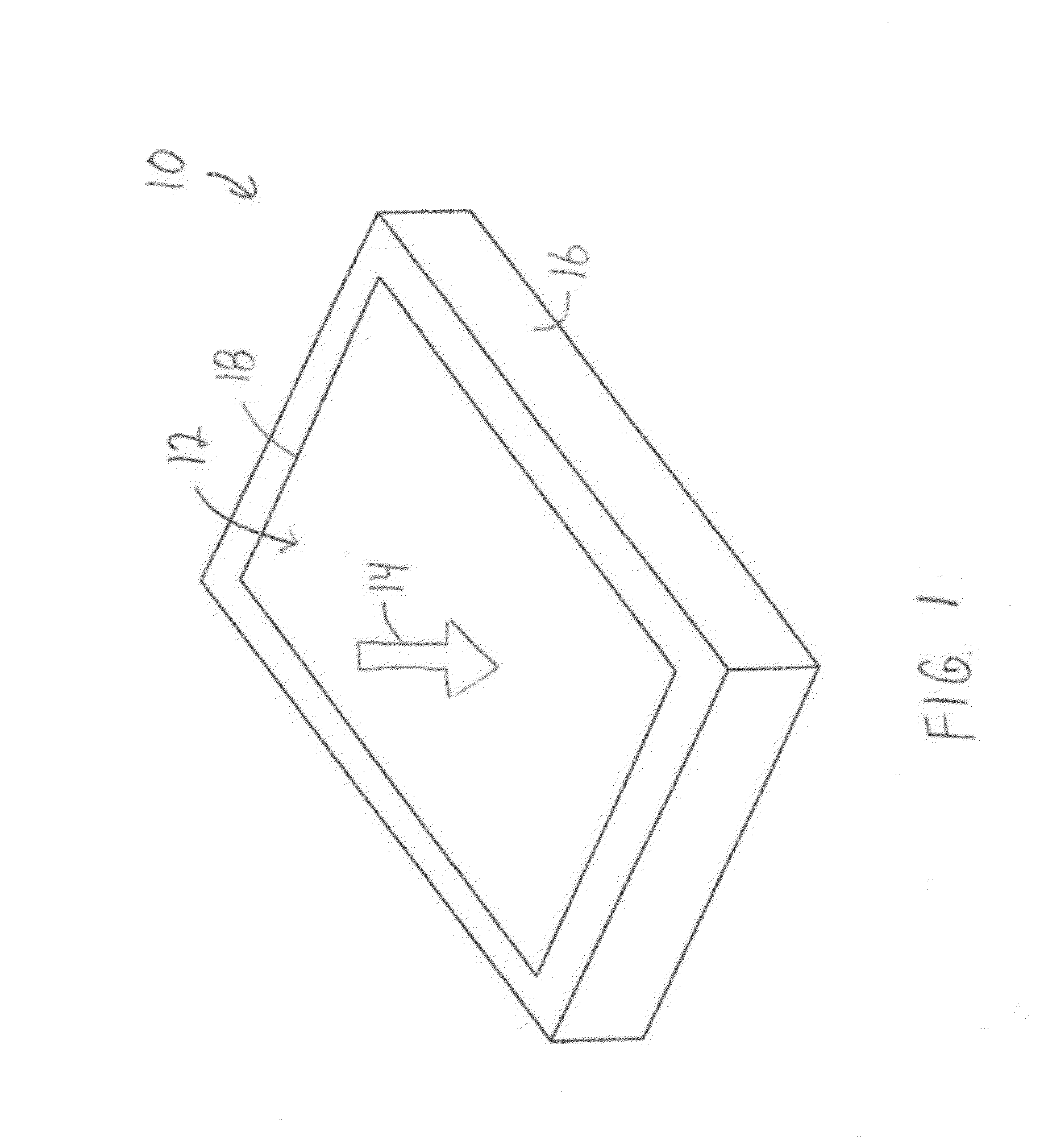
[0009]The first electrode is coupled with the touch surface and is configured to receive a first haptic actuation electric potential. The second electrode is coupled with the touch surface and is configured to receive a different, second haptic actuation electric potential having an opposite polarity than the first haptic actuation potential. The first and second electrodes generate an electrostatic force that is imparted on one or more appendages of an operator that touches the touch surface above both the first electrode and the second electrode in order to generate a haptic effect.

Problems solved by technology

Such mechanical vibration can have certain drawbacks, such as relatively high energy consumption.
Furthermore, such mechanical vibration may not support multitouch, in which multiple fingertips simultaneously or concurrently engage the display screen in more than one location.
As a result, the haptic effects provided to each fingertip cannot be individually controlled (e.g., different from each other) at the same time.
These devices use electric fields to apply vibratory forces directly to the fingertips, and therefore do not have any moving mechanical parts.
These devices, however, produce relatively small forces and can require relatively high voltages (e.g., 750-1000 volts).

Method used


Image

  • Touch interface device having an electrostatic multitouch surface and method for controlling the device
  • Touch interface device having an electrostatic multitouch surface and method for controlling the device
  • Touch interface device having an electrostatic multitouch surface and method for controlling the device

Examples


Embodiment Construction

[0033]In accordance with one or more embodiments described herein, several approaches for generating relatively large changes in normal forces applied to appendages of an operator of a touch interface device when the appendages engage a touch surface on a touch sensitive screen of the touch interface device. The appendages are described herein as fingertips, but alternatively or additionally may include other appendages, such as toes or even other body parts such as the palm. Changing these normal forces results in relatively large changes in the frictional force between the fingertip and the touch surface of the touch sensitive screen. The changes in normal forces can be implemented using electrostatics. In one embodiment, to produce relatively large forces, a voltage is applied to one or more conductors or electrodes disposed below the touch surface and the voltage is modulated at a frequency. As used herein, the term “conductor” or “electrode” includes a conductive body to which ...


PUM


Abstract

A touch interface device includes a touch surface, a first electrode, and a second electrode. The first electrode is coupled with the touch surface. The first electrode also configured to receive a first haptic actuation electric potential. The second electrode is coupled with the touch surface. The second electrode also is configured to receive a different, second haptic actuation electric potential having an opposite polarity than the first haptic actuation potential. The first and second electrodes generate an electrostatic force that is imparted on one or more appendages of an operator that touches the touch surface above both the first electrode and the second electrode in order to generate a haptic effect.

Description

CROSS-REFERENCE TO RELATED APPLICATIONS[0001]This application claims priority benefit of U.S. Provisional Application No. 61 / 484,564, which also was filed on 10 May 2011 and is entitled “A Touch Interface Device Having An Electrostatic Multitouch Surface” (referred to herein as the “'564 application”). This application is related to U.S. Provisional Application No. 61 / 484,544, which was filed on 10 May 2011 and is entitled “A Touch Interface Device Able To Apply Controllable Shear Forces To A Human Appendage” (referred to herein as the “'544 application”). This application also is related to U.S. application Ser. No. ______, which is filed concurrently with the present application and is entitled “A Touch Interface Device And Method For Applying Controllable Shear Forces To A Human Appendage” (referred to herein as the “'______ application”). The entire disclosures of the '564 application, the '544 application, and the '______ application are incorporated by reference.STATEMENT REGA...

Claims


Application Information

Patent Timeline
IPC IPC(8): G06F3/041
CPCG06F3/016G06F3/0416G06F3/041G06F3/044G06F3/0446G06F3/0445G06F3/0412G06F3/045G06F3/046G06F2203/04101G06F2203/04105G06F2203/04112G06F2203/04113
Inventor COLGATE, J. EDWARDPESHKIN, MICHAEL A.
Owner NORTHWESTERN UNIV
Learn More