
Method and system for sensing the position of a vehicle

Active Publication Date: 2012-11-15
ZENO TRACK
View PDF5 Cites 25 Cited by
  • Summary
  • Abstract
  • Description
  • Claims
  • Application Information

AI Technical Summary

Benefits of technology

[0033]The advantageous effects that accompany the inventive device have already been described above in the context of the inventive method, so that for purposes of avoiding repetition reference is made to the above statement.
that accompany the inventive device have already been described above in the context of the inventive method, so that for purposes of avoiding repetition reference is made to the above statement.

Problems solved by technology

This means that an exact determination of absolute position is not possible, instead a probable position is determined by way of an exclusion method; while in the best-case scenario this does indeed correspond to the actual absolute position, it can also deviate significantly from the latter.
The determination of position by means of laser radar scanning in accordance with known art encounters its limitations in particular if the environment is similar or the distances involved prevent or place limits on the scanning procedure (e.g. in the case of an empty warehouse with supporting pillars, with empty storage areas, or storage areas with stored goods items that have identical structures, or in the external environment).
However, this system has the disadvantage that no determination of position is possible if there is no marker in the field of view of the camera, i.e. no other system is available to execute a determination of position.
This in turn means that the storage depot must be fitted with very many markers; this leads to an extremely high level of expenditure, particularly in the case of large storage depots.
Moreover, by virtue of the attachment of markers to the ceiling, this system of known art is disadvantageously limited to an internal environment.
Apart from the fact that is in actual fact not possible to differentiate between ceiling lights that are usually of identical design by way of an optical sensor, e.g. using a CCD camera or photodiode array, or at best only with a high error rate, a trailing wheel is provided for purposes of registering the relative movement of the driverless vehicle; this is connected with the vehicle via a vertical axis about which it can rotate.
In practice, however, such trailing wheels have proved to be extremely inaccurate (in particular as a result of problems with slip and drift).
What is particularly disadvantageous here is the fact that the installation of the reflecting markers in the ceiling region of a warehouse is very labour and cost intensive, and moreover the registration of the reference position is not always reliably guaranteed.
Furthermore problems arise in the measurement of the relative movement by means of the wheel encoder and gyroscope in terms of slip and drift of the vehicle (e.g. spinning of the wheels), so that often the relative distance covered is incorrectly determined.
An application of this method in an external environment (with no roof) of a storage depot is impossible, or only if linked with substantial installation and cost expenditures.
As a result of the fact that the camera must be attached near the floor, contamination of the camera optics occurs to a large extent; this can lead to a high level of inaccuracy, or a failure, in the registration of the relative movement.
However, what is particularly disadvantageous, even in the case of EP 1 916 504, is the fact that, now as before, for purposes of registering the absolute reference position a very laborious and cost intensive installation of reflecting markers in the ceiling region is required.
Here too this takes the form of a technically complex system with a multiplicity of sensors, which, in particular in cases where large surface areas are to be defined, are the cause of extremely high installation and investment expenditures.
However, what is particularly disadvantageous is the fact that the registration of a reference position of a vehicle is only possible if it drives over a transponder, and thus there is no continuous registration of a reference position of a vehicle; this has a particularly disadvantageous consequence when e.g. setting down goods items in areas of the storage depot that are not fitted with transponders.

Method used


Image

  • Method and system for sensing the position of a vehicle
  • Method and system for sensing the position of a vehicle
  • Method and system for sensing the position of a vehicle

Examples


examples

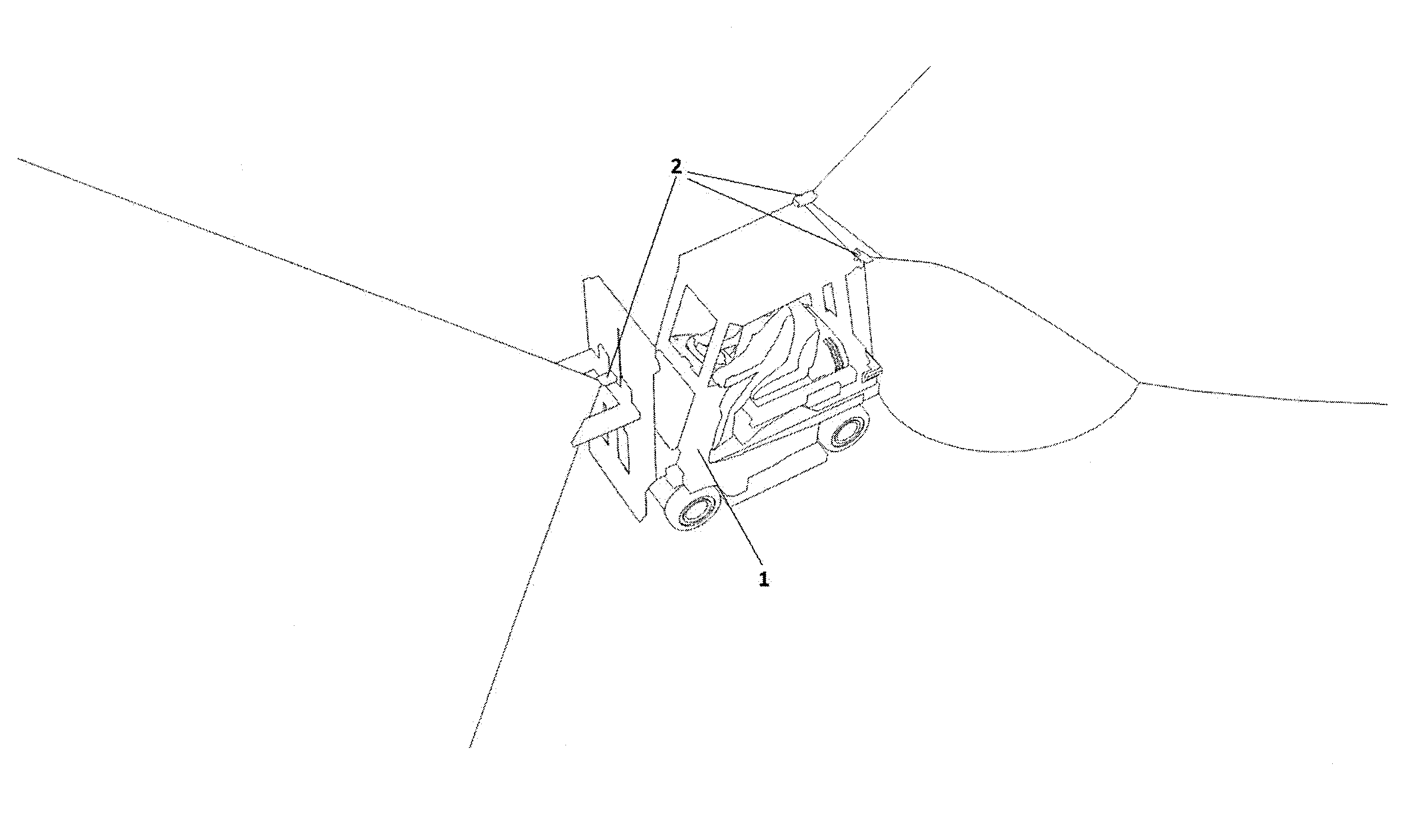
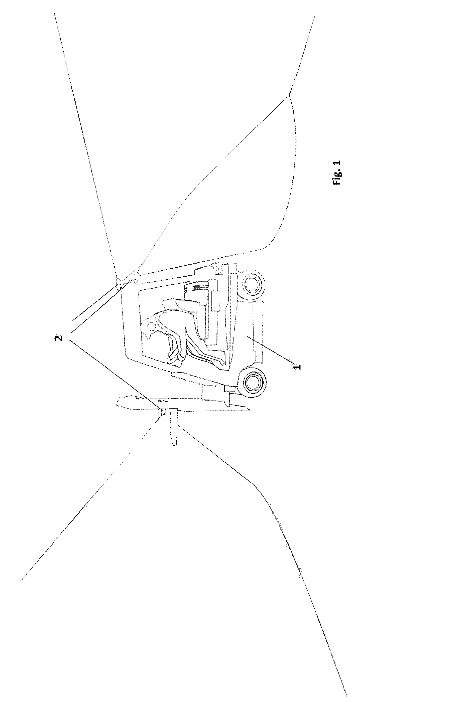
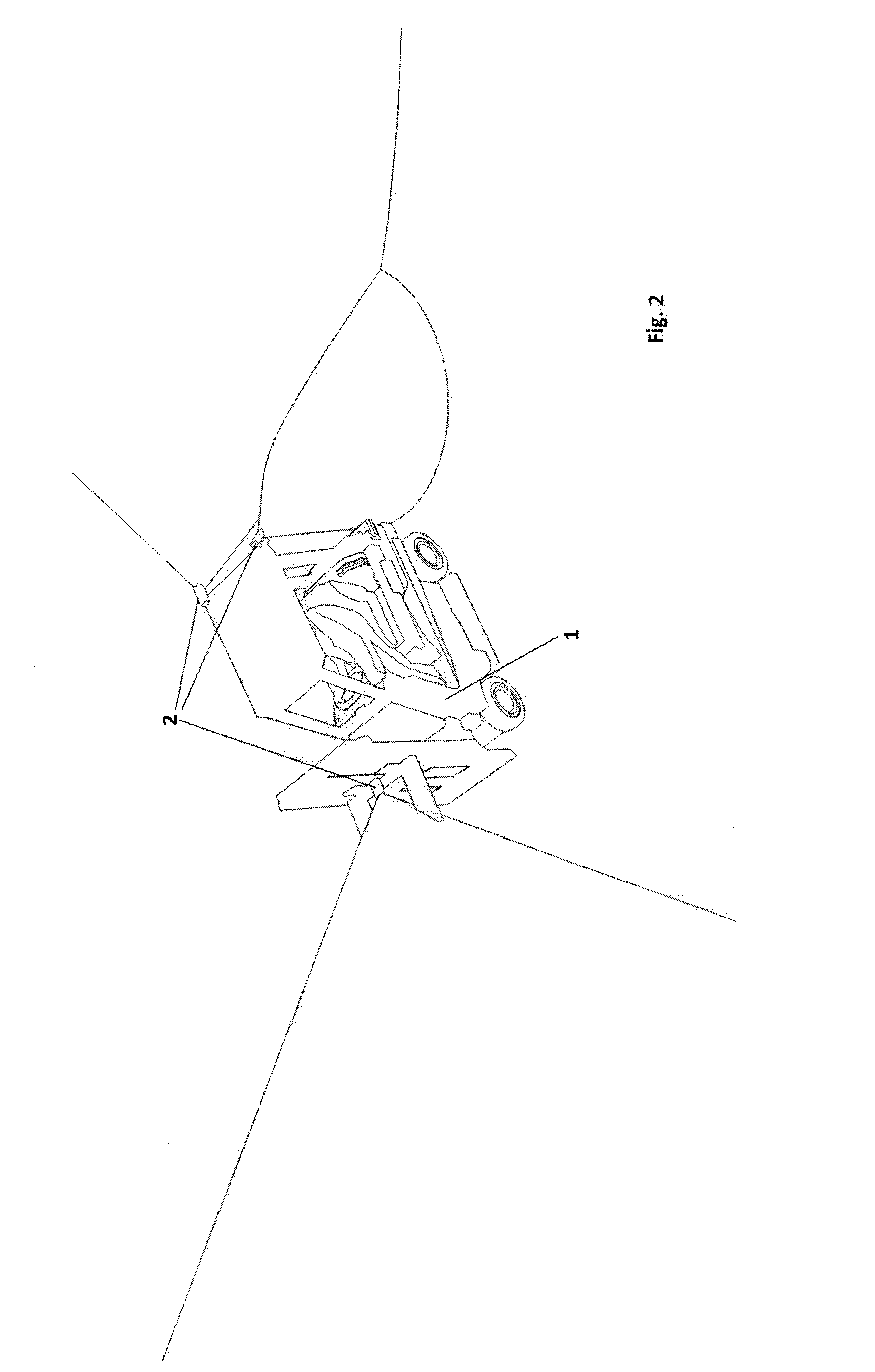
[0043]In FIGS. 1 and 2 an example of a vehicle 1 is represented, the position of which is to be determined in a defined region 3 represented in FIG. 3, e.g. a storage depot. Here it can be seen that the vehicle 1 has a plurality of imaging sensor devices, preferably digital cameras 2. The attachment to the vehicle 1 is preferably undertaken such that the field of view registered by the digital camera 2 is directed rearwards of the vehicle 1. This is advantageous, since in the case of industrial goods-handling vehicles the field of view in the direction forwards of the vehicle 1 is often restricted when transporting goods items. When using a plurality of digital cameras 2 they can be attached—as can be seen in FIG. 1—such that the field of view of the cameras 2 is directed in both the rearward and forward directions, wherein, needless to say, the lateral environment of the vehicle 1 is also registered with the cameras 2.

[0044]Depending upon the circumstances of the environmental infr...


PUM


Abstract

The invention concerns a method and a system for purposes of registering the position of a vehicle (1) in a defined region (3), wherein a digital map of the defined region (3) is created, having a defined coordinates system, wherein the digital map includes stationary reference features (T1) with a unique identifying feature, before digital images are recorded of at least a sub-region of the defined region (3), preferably of the whole defined region (3), for purposes of registering and detecting further reference features (T1, T2, T3), wherein stationary and / or temporary reference features (T2, T3) without unique identifying features are also registered and detected, and are added to the digital map and / or an associated buffer store, so that the absolute position of the vehicle (1) in the defined region (3) can subsequently be determined, in that a digital image of a portion of the defined region (3) is recorded by the vehicle (1), and in the digital image reference features (T1, T2, T3) are detected and optionally identified, wherein the determination of absolute position is undertaken on the basis of the stationary and / or temporary reference features (T1, T2, T3) that have been detected and optionally identified.

Description

PRIORITY INFORMATION[0001]This application is a national phase application of PCT / AT2011 / 000030, filed Jan. 18, 2011, which claims priority to Austrian Patent Application No. A 60 / 2010 filed Jan. 18, 2010, the disclosures of which are incorporated herein by reference in their entirety.FIELD OF THE INVENTION[0002]The invention concerns a method and a system for purposes of registering the position of a vehicle in a defined region.BACKGROUND OF THE INVENTION[0003]The registering of the current position of a vehicle in a defined region is of great importance in a very wide range of applications. For example the determination of the positions of industrial goods-handling vehicles (e.g. forklift trucks) in the field of storage logistics (management of e.g. production stores, distribution stores) is of great importance, since by this means, for example, the optimisation of logistical processes and automatic tracing of batches of goods items is made possible. For this purpose a very wide v...

Claims


Application Information

Patent Timeline
IPC IPC(8): G06K9/36H04N7/18
CPCG05D1/0274G01C21/005
Inventor ESSATI, ALECWILDENAUER, HORST
Owner ZENO TRACK
Learn More