Leak detection apparatus for aircraft bleed air systems

a technology of leak detection and aircraft ducting, which is applied in the direction of fluid tightness measurement, energy-efficient board measurement, instruments, etc., can solve the problems of affecting the efficiency of airline operations, passenger inconvenience, and temperature well above the safe operating limits of aircraft type composite materials, etc., to achieve effective and reliable structure

Inactive Publication Date: 2012-11-15
ARROWHEAD PROD
View PDF17 Cites 24 Cited by
  • Summary
  • Abstract
  • Description
  • Claims
  • Application Information

AI Technical Summary

Benefits of technology

[0016]Accordingly, it is a general object of the present invention to provide an improved leak detection apparatus for aircraft bleed air systems. It is a more particular object of the present invention to provide an improved leak detection apparatus for aircraft bleed air systems which utilizes an effective and reliable structure for collecting leaking bleed air between the system duct and shroud and for directing the leaking bleed air toward temperature sensing wires supported by the leak detection apparatus. It is a further object of the present invention to provide an improved leak detection apparatus for aircraft bleed systems which further vents collected bleed air leakage outwardly for combination with cooler ambient air and avoidance of aircraft structural elements.

Problems solved by technology

Unfortunately, such elevated temperatures are well above the safe operating limits of the materials typically used in aircraft construction.
Similarly, most modern aircraft type composite materials cannot be safely used in environments above 250 degrees Fahrenheit.
In addition, the outer shroud tends to confine and collect bleed air leaking from the interior duct.
Unplanned landings, aborts and schedule delays caused by false alarms within the bleed air leak detection system negatively impacts airline efficiency of operation and passenger inconvenience.
A pair of heat sensitive wires are coupled to the manifold and are thus subjected to high temperature bleed air leaking from the interior duct.

Method used


Image

  • Leak detection apparatus for aircraft bleed air systems
  • Leak detection apparatus for aircraft bleed air systems
  • Leak detection apparatus for aircraft bleed air systems

Examples


Embodiment Construction

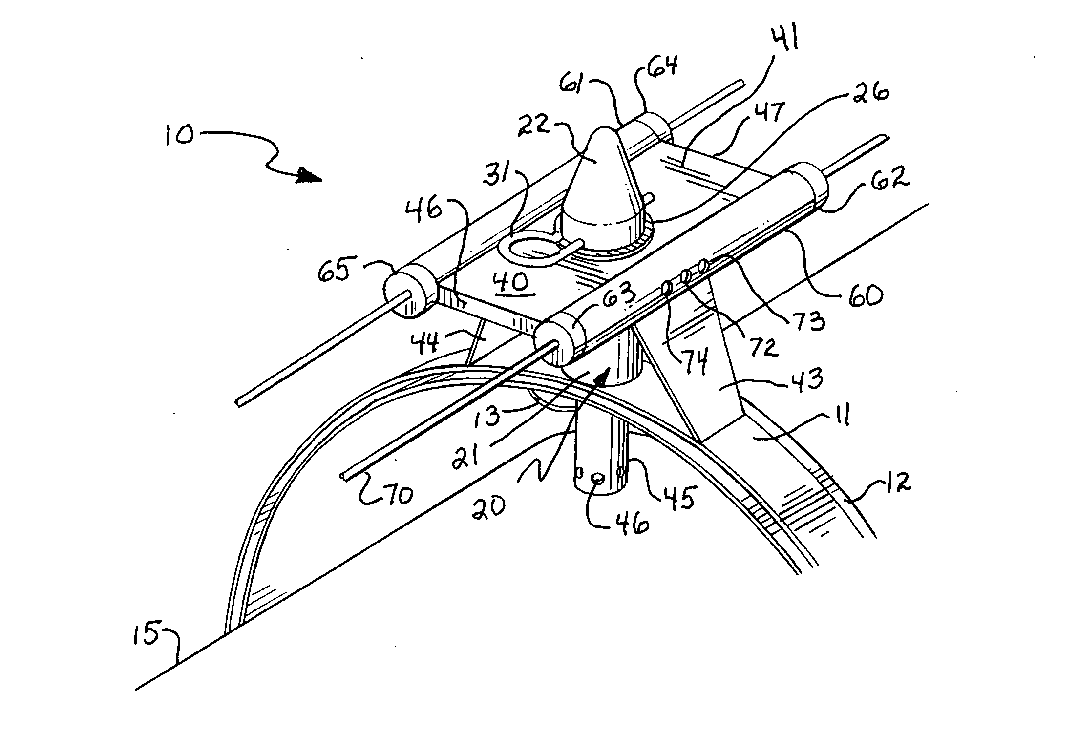
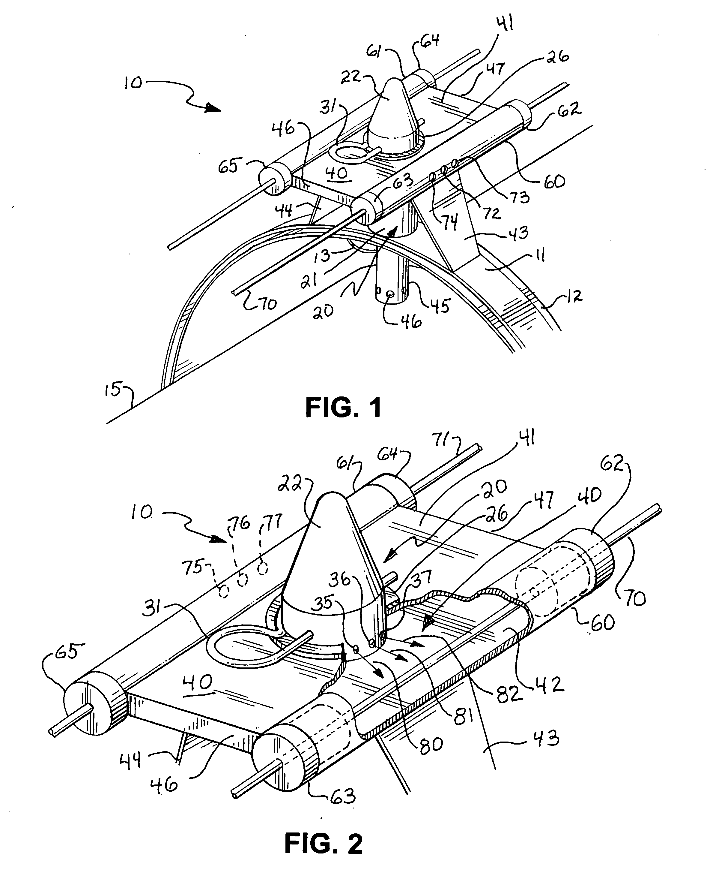
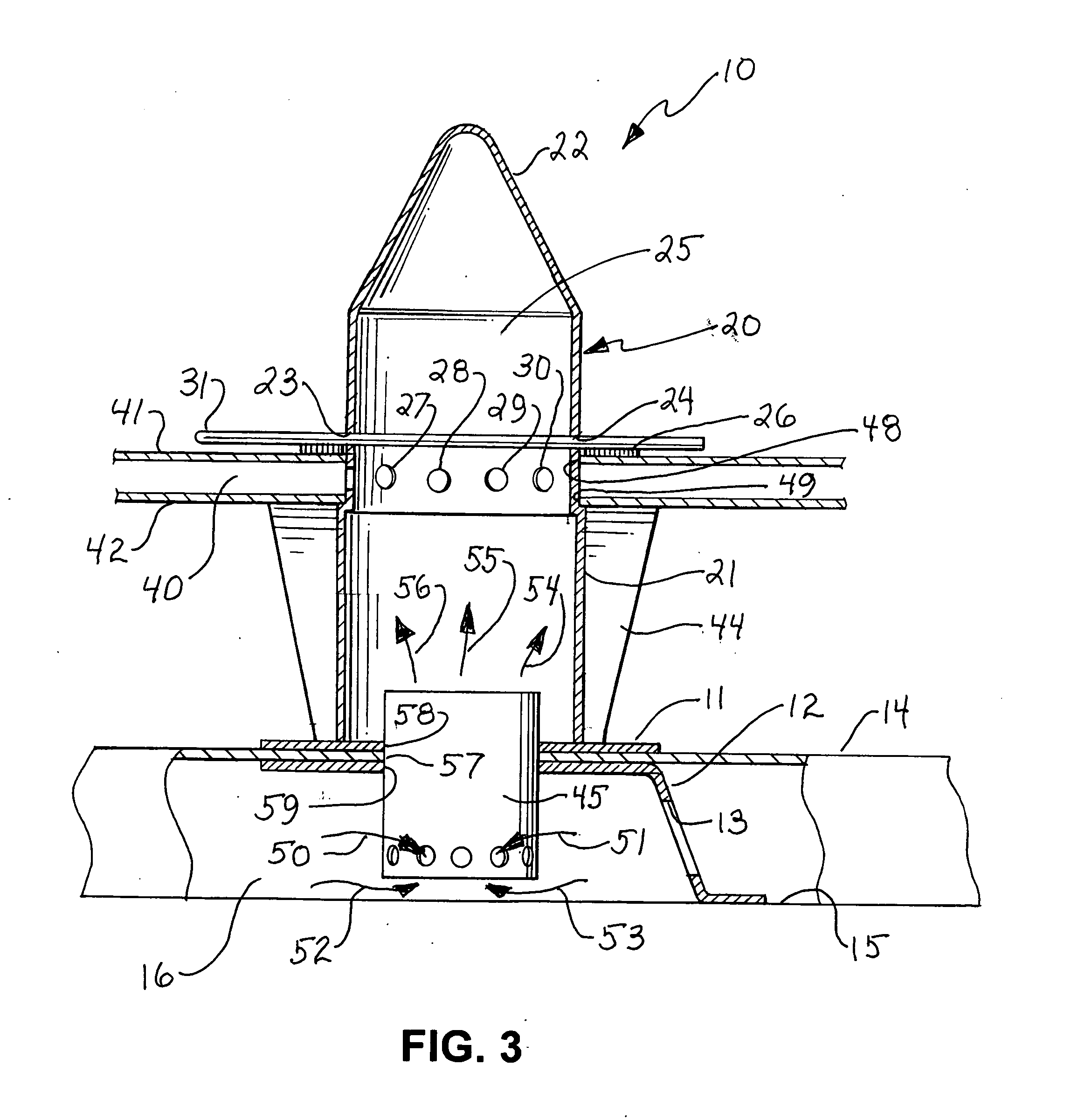
[0022]FIG. 1 sets forth a perspective view of a bleed air leak detector constructed in accordance with the present invention and generally referenced by numeral 10. Bleed air leak detector 10 is supported by a spacer 12 and a sleeve 11. With temporary reference to FIG. 3, it will be noted that sleeve 11 is supported on the exterior surface of a shroud 14 while spacer 12 is positioned upon bleed air duct 15 underlying the interior surface of shroud 14. Accordingly and as is also better seen in FIG. 3, sleeve 11 and spacer 12 captivate shroud 14.

[0023]Returning to FIG. 1 for purposes of illustration, shroud 14 is omitted from the figure and thus bleed air duct 15 is shown having sleeve 11 and spacer 12 supported spaced from and encircling bleed air duct 15. Bleed air duct 15 and shroud 14 (seen in FIG. 3) will be understood to be fabricated in general accordance with conventional fabrication. Sleeve 11 is preferably fabricated of a suitable strong material such as metal or composite m...


PUM

PropertyMeasurementUnit
temperaturesaaaaaaaaaa
temperatureaaaaaaaaaa

Abstract

A leak detection apparatus for aircraft bleed air systems includes a supporting spacer positioned within the shroud and supported upon the bleed air duct of the aircraft. A sleeve supported on the exterior of the shroud further supports a plenum having generally cylindrical sensor tubes through which sensor wire sets pass. A director positioned within the shroud above the bleed air duct is coupled to a generally cylindrical accumulator which in turn is in communication with the plenum. Appropriate apertures are provided to vent and direct bleed air from the shroud interior to the sensor wire sets and thereafter vent outwardly into cooler ambient air. The sensor wire sets respond to the temperature of the bleed air leakage to trigger alarm apparatus.

Description

FIELD OF THE INVENTION[0001]This invention relates generally to bleed air ducting systems of the type used in aircraft and relates particularly to leak detection apparatus used therein.BACKGROUND OF THE INVENTION[0002]Modern aircraft utilize fluid transport ducting systems to circulate high-pressure, high-temperature air ported from one of the aircraft turbine engine compressor stages. Because this high-pressure, high-temperature air is diverted or “bled” from a turbine compressor stage, such circulation systems are generally referred to in the art as “bleed air” systems.[0003]For the most part, this high-pressure, high-temperature bleed air is used within the aircraft for deicing the leading edges of wings and stabilizers as well as engine inlets. Bleed air is also used for cabin pressurization and cabin heating.[0004]Because bleed air may exceed temperatures of 1,350 degrees Fahrenheit it is an excellent high-volume, high-capacity heat source which readily meets the above-mentione...

Claims


Application Information

Patent Timeline
Patent Type & Authority Applications(United States)
IPC IPC(8): G01N25/72
CPCB64D13/00B64D2013/0618Y02T50/56G01M3/165G01M3/045Y02T50/50
Inventor THOMPSON, WILLIAM W.HARWOOD, ALLEN W.STARK, GLENN
Owner ARROWHEAD PROD
Why Eureka
Try Eureka