Shielding structure for optical sub-assembly for transceivers

a technology of optical sub-assembly and shielding structure, which is applied in the direction of optics, instruments, optical light guides, etc., can solve the problems of communication interference and need to be overcom

Inactive Publication Date: 2012-11-15
EZCONN
View PDF1 Cites 45 Cited by
  • Summary
  • Abstract
  • Description
  • Claims
  • Application Information

AI Technical Summary

Benefits of technology

[0006]A primary object of the present invention is to provide a shielding structure for optical sub-assembly for transceivers, which can avoid electromagnetic interference of external electromagnetic wave with the optical sub-assembly for transceivers.

Problems solved by technology

This will lead to interference with the communication and needs to be overcome.

Method used


Image

  • Shielding structure for optical sub-assembly for transceivers
  • Shielding structure for optical sub-assembly for transceivers
  • Shielding structure for optical sub-assembly for transceivers

Examples


Embodiment Construction

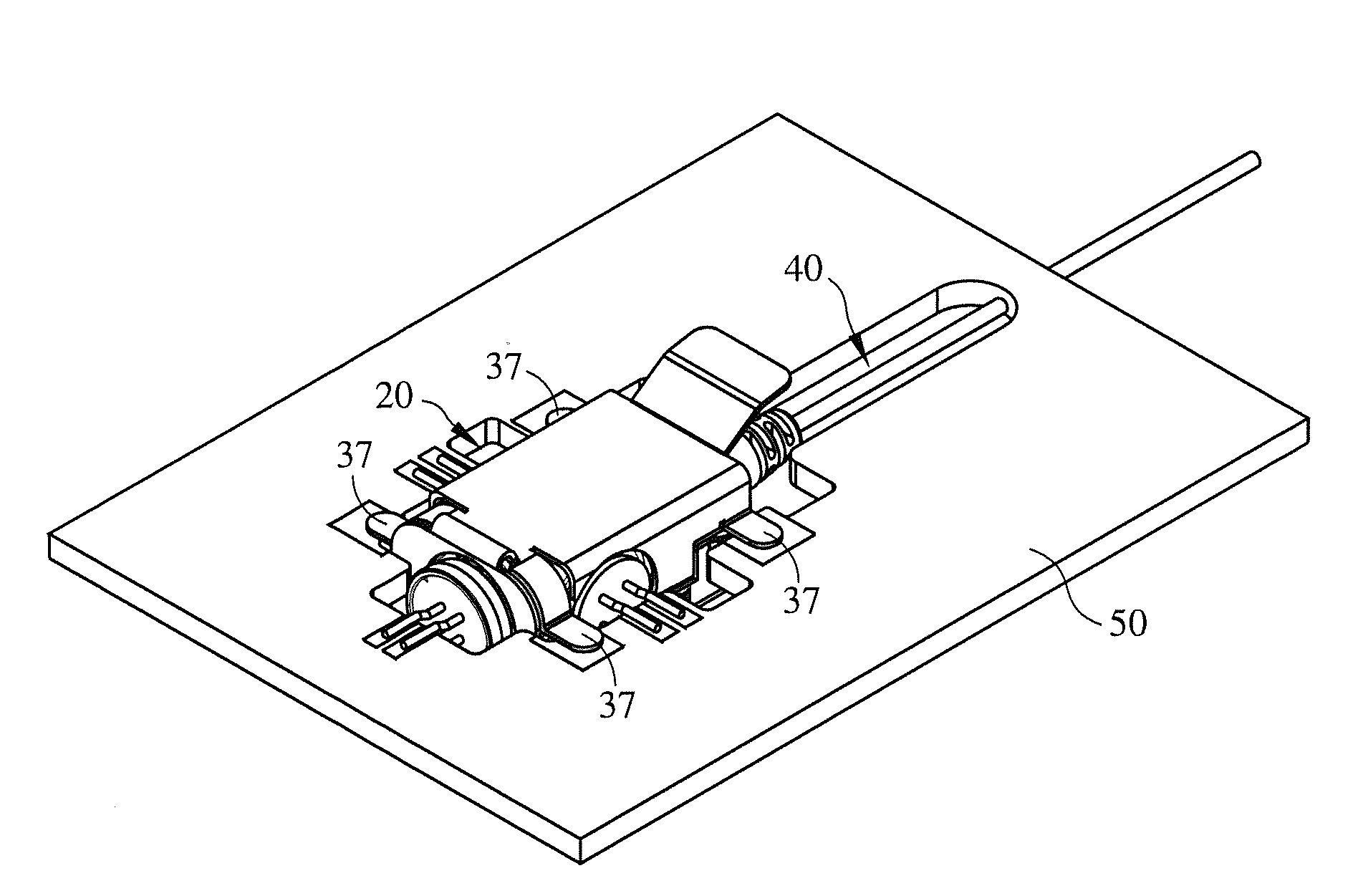
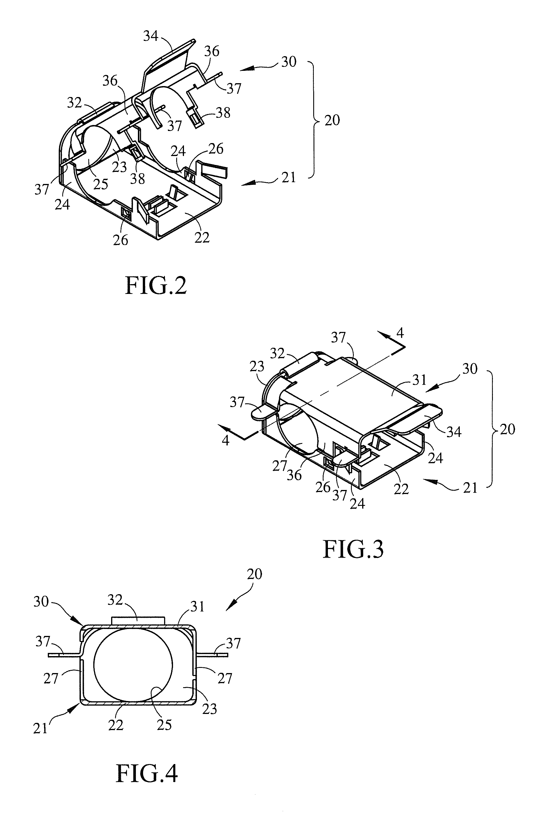
[0015]Please refer to FIGS. 2 to 4. The shielding structure 20 of the present invention is applicable to various optical sub-assemblies for transceivers, such as BOSA and TRI-DI OSA. The shielding structure 20 includes a housing 21 and a movable cover 30. The housing 21 has a bottom board 22, a front end board 23 upward extending from a front end of the bottom board 22 and two sideboards 24 upward extending from a left side and a right side of the bottom board 22.

[0016]The front end board 23 is formed with a connection port 25 with a diameter approximately equal to that of the digital signal transmitter 44 of the tri-direction optical sub-assembly 40 (as shown in FIG. 5A). Accordingly, the digital signal transmitter 44 can pass through the connection port 25.

[0017]The movable cover 30 includes a plate main body 31. The plate main body 31 has a connection end 32 connected with a top end of the front end board 23 of the housing 21 and a press end 34 opposite to the connection end 32. ...


PUM


Abstract

A shielding structure for optical sub-assembly for transceivers includes a housing and a movable board. The housing has a bottom board, a front end board upward extending from a front end of the bottom board and two sideboards upward extending from a left side and a right side of the bottom board. The movable cover includes a plate main body. The plate main body has a connection end connected with the front end board of the housing and a press end opposite to the connection end. The movable cover further includes two sideboards downward extending from a left side and a right side of the plate main body. When installing the optical sub-assembly for transceivers into the shielding structure, the press end of the movable cover is pressed down until the movable cover is engaged with the housing in a closed state so as to avoid electromagnetic interference.

Description

BACKGROUND OF THE INVENTION[0001]1. Field of the Invention[0002]The present invention relates to a shielding structure, and more particularly to a shielding structure for optical sub-assembly for transceivers.[0003]2. Description of the Related Art[0004]In an optical fiber communication system, optical sub-assembly for transceivers is an important medium for conversion between optical signals and electrical signals. The optical sub-assembly for transceivers related to the present invention can be classified into bi-direction optical sub-assembly (BOSA) capable of receiving bi-direction signals in the same optical fiber and tri-direction optical sub-assembly (TRI-DI OSA) capable of receiving tri-direction signals in the same optical fiber.[0005]As shown in FIG. 1, taking the tri-direction optical sub-assembly as an example, the tri-direction optical sub-assembly 10 is fixed on a circuit board 11 by means of soldering. The tri-direction optical sub-assembly 10 is not equipped with any...

Claims


Application Information

Patent Timeline
Patent Type & Authority Applications(United States)
IPC IPC(8): G02B6/36
CPCG02B6/4277G02B6/4246
Inventor WU, CHIN-TSUNGCHENG, KUEI-HSIANG
Owner EZCONN
Why Eureka
Try Eureka