Lever-type connector

a connector and lever-type technology, applied in the direction of coupling device connection, coupling parts engagement/disengagement, electrical apparatus, etc., can solve the problem of difficult finger insertion into the insertion space, and achieve the effect of excellent space efficiency

Active Publication Date: 2012-11-15
SUMITOMO WIRING SYST LTD
View PDF9 Cites 4 Cited by
  • Summary
  • Abstract
  • Description
  • Claims
  • Application Information

AI Technical Summary

Benefits of technology

[0009]The invention relates to a lever-type connector with a housing that is connectable to a mating connector. A lever is mounted rotatably or pivotably on the housing. A resiliently deformable lock arm is formed on the lever and projects substantially along a rotating direction of the lever. A base piece is formed on the housing and stands in a direction crossing a connecting direction to the mating connector. Thus, the base piece and the lock arm do not project ...

Problems solved by technology

Therefore, it is difficult to ins...

Method used


Image

  • Lever-type connector
  • Lever-type connector
  • Lever-type connector

Examples


Embodiment Construction

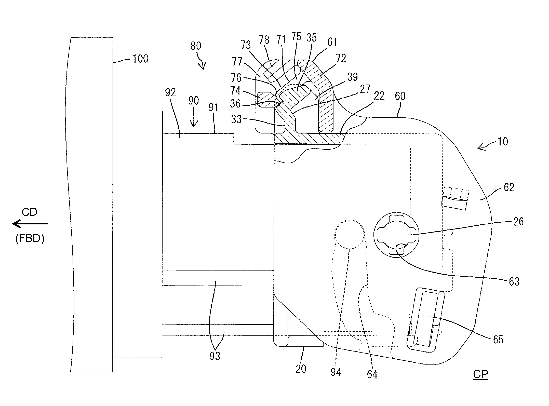
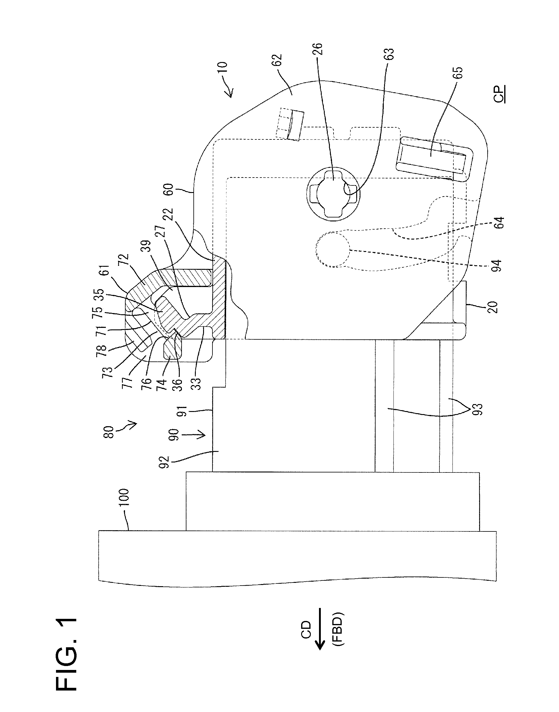
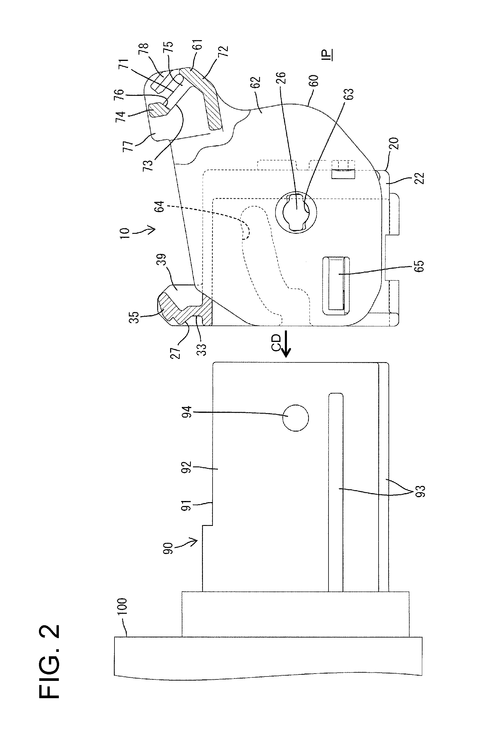
[0028]A lever-type connector according to the invention is identified by the number 10 in FIGS. 1 to 8. The connector 10 includes a housing 20 and a lever 60. The housing 20 is connectable to a mating connector 90 in a connecting direction CD. In the following description, an end to be connected to the mating connector 90 is referred to as the front concerning forward and backward directions FBD.

[0029]As shown in FIG. 2, the mating connector 90 is mounted directly on an external member 100 such as an auxiliary machine and includes a mating housing 91 made e.g. of synthetic resin. The mating housing 91 has a substantially rectangular tubular receptacle 92 that opens forward and unillustrated male tabs project into the receptacle 92. Long narrow ribs 93 are formed on an outer side surface and lower surface of the receptacle 92 and extend in forward and backward directions FBD. Substantially cylindrical cam followers 94 project from the outer side surfaces of the receptacle 92.

[0030]Th...


PUM


Abstract

A lever (60) is formed with a resiliently deformable lock arm (71) projecting substantially along a rotating direction of the lever (60). A housing (20) is formed with a base piece (27) standing in a direction crossing a connecting direction to a mating connector (90). An engaging portion (35) for holding the housing (20) and the mating connector (90) in the properly connected state by being resiliently engaged with a leading end part of the lock arm (71) is formed on a leading end part of the base piece (27). A recess (33) into which a finger (50) is insertable to disengage the engaging portion (35) and the lock arm (71) is formed in a base end part of the base piece (27).

Description

BACKGROUND OF THE INVENTION[0001]1. Field of the Invention[0002]The invention relates to a lever-type connector.[0003]2. Description of the Related Art[0004]Japanese Publication No. 2003-178837 discloses a connector with a housing and a lever to be mounted rotatably on the housing. The housing is connectable to a mating connector as the lever is rotated. The lever has an operating portion and a resiliently deformable lock arm projects from the operating portion substantially along a rotating direction of the lever. A base piece projects back from the rear end of the upper surface of the mating connector and an engaging portion projects up on a rear end part of the base piece.[0005]The lever is engaged with the mating connector and is rotated forward from the back side. The lever exhibits a force multiplying action that enables the housing to be connected to the mating connector with a small operation force. A leading end part of the lock arm resiliently engages the engaging portion ...

Claims


Application Information

Patent Timeline
IPC IPC(8): H01R13/62
CPCH01R13/62955
Inventor UCHIDA, TOMOHISA
Owner SUMITOMO WIRING SYST LTD
Why Eureka
Try Eureka