Current sensor for electric wire

a current sensor and electric wire technology, applied in the direction of resistance/reactance/impedence, voltage-current phase angle, instruments, etc., can solve the problems of generation of measurement errors and inability to achieve precise measurement, so as to reduce the influence of external magnetic fields and reduce the effect of positional displacement of electric wires

Inactive Publication Date: 2012-11-15
ALPS GREEN DEVICES
View PDF2 Cites 46 Cited by
  • Summary
  • Abstract
  • Description
  • Claims
  • Application Information

AI Technical Summary

Benefits of technology

[0009]In view of the above situation, the present invention provides a current sensor that reduces the influen

Problems solved by technology

However, such a method based on detection of the strength of a magnetic field has a problem in that variation in the distance between the electric wire and the current sensor due to the positional displacement of the electric wire causes generation of a measurement error.
However, with the configuration described above, a

Method used


Image

  • Current sensor for electric wire
  • Current sensor for electric wire
  • Current sensor for electric wire

Examples


Embodiment Construction

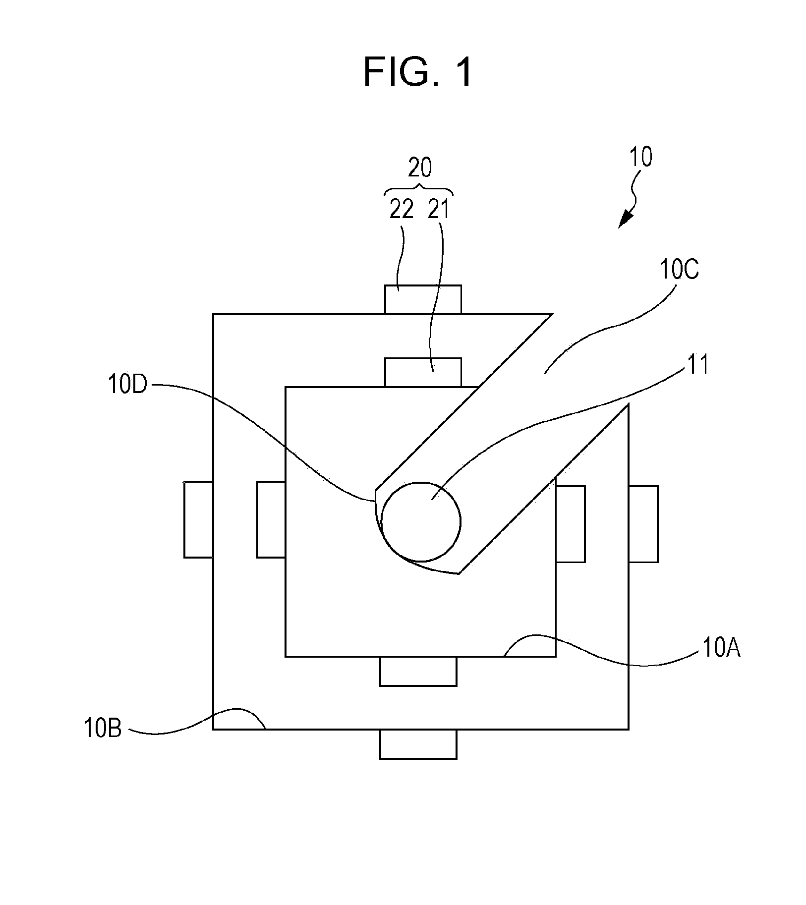
[0031]Hereinafter, a current sensor according to an embodiment of the present invention is described with reference to FIGS. 1 to 5.

[0032]Referring to FIG. 1, a current sensor of the present invention preferably includes a square support body 10, and the support body 10 has inner surfaces 10A and outer surfaces 10B formed correspondingly to the four sides thereof. One corner of the support body 10 is preferably cut off so as to form an electric wire guide 10C, which can guide an electric wire 11 to be measured to the center of the support body 10. The electric wire guide 10C extends to the center of the support body 10, and the end of the extended portion may form an electric wire holding portion 10D, where the guided electric wire 11 to be measured is held at the center of the support body 10.

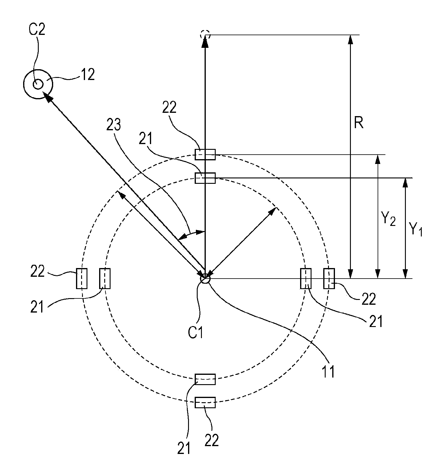
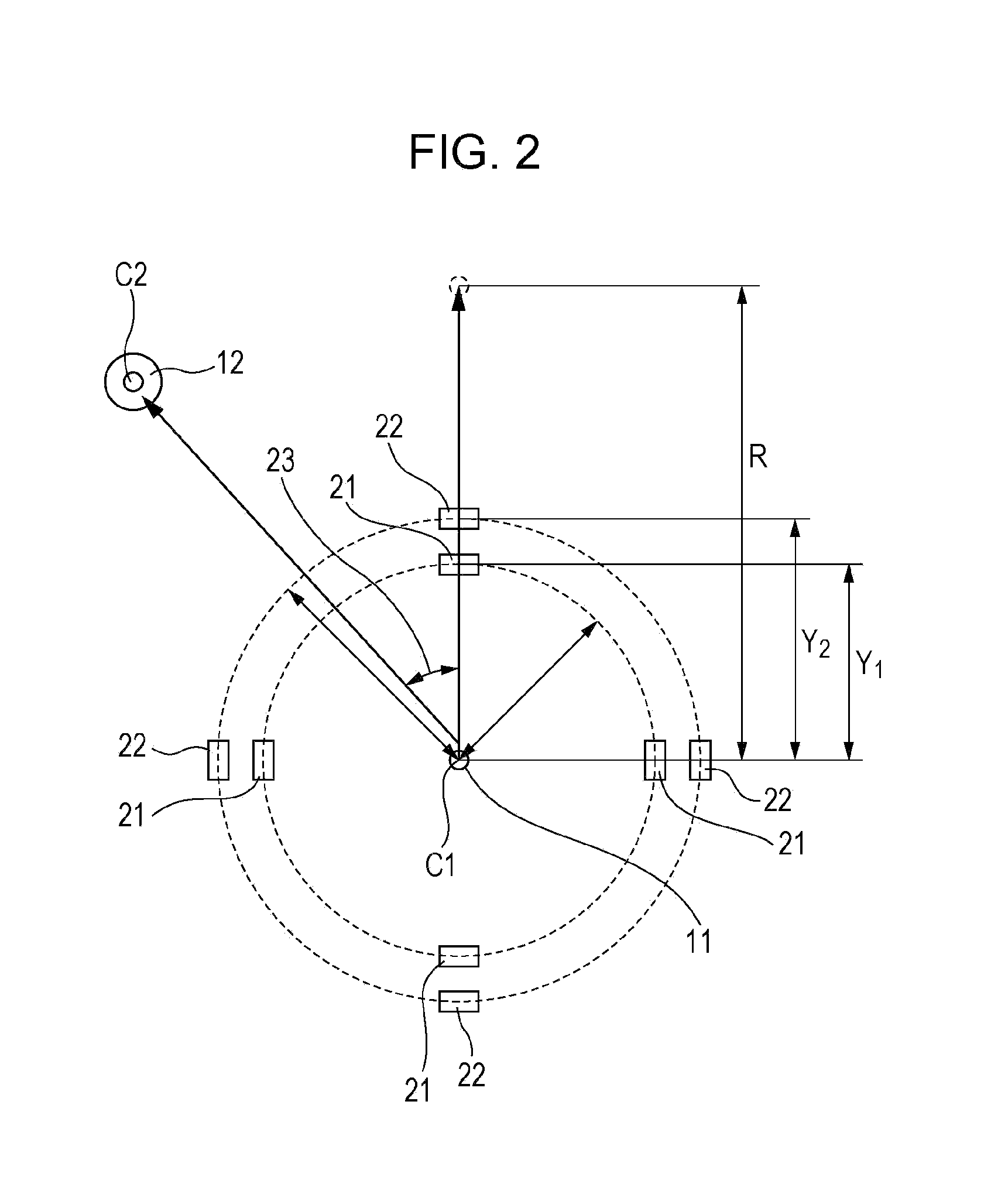
[0033]Inner magnetic sensor elements 21 and outer magnetic sensor elements 22 are arranged, so as to be opposite each other, respectively on the inner surface 10A and the outer surface 10B alo...


PUM


Abstract

A current sensor includes an electric wire to be measured, a guide portion for guiding the electric wire to be measured, a holding portion for holding the electric wire to be measured, and four pairs of magnetic sensor elements arranged at intervals of 90 degrees along a circumference around a center axis which is a virtual arrangement axis of the electric wire to be measured. The outputs of the magnetic sensor elements of each pair are appropriately linearly combined and the linearly combined outputs of all the pairs are added. Hence, a space for guiding the electric wire to be measured can be easily allocated, and the effects of variation sources such as the displacement of the electric wire to be measured, a constant external magnetic field, and an external magnetic field generated by a neighboring electric wire are compensated for, whereby a small high-accuracy current sensor is provided.

Description

CLAIM OF PRIORITY[0001]This application claims benefit of Japanese Patent Application No. 2011-103940 filed on May 9, 2011, which is hereby incorporated by reference.BACKGROUND OF THE INVENTION[0002]1. Field of the Invention[0003]The present invention relates to current sensors for detecting, for example, the value of a current flowing through an electric wire.[0004]2. Description of the Related Art[0005]Related art current sensors that have been used for detecting the value of a current flowing through an electric wire include a current sensor that detects the strength of a magnetic field by arranging a magnetic sensor element at a position spaced apart from the electric wire by an appropriate distance, thereby detecting the value of a current flowing through an electric wire at that position.[0006]However, such a method based on detection of the strength of a magnetic field has a problem in that variation in the distance between the electric wire and the current sensor due to the ...

Claims


Application Information

Patent Timeline
IPC IPC(8): G06F19/00
CPCG01R15/207G01R15/20
Inventor FUKUI, HIROFUMI
Owner ALPS GREEN DEVICES
Why Eureka
Try Eureka