
Balance Chair

a balance chair and chair body technology, applied in the field of chairs, can solve the problems of excessive or premature wear of the chair, and achieve the effects of less abrupt pivoting, less abrupt leaning, and preventing the user from excessive leaning or falling sideways

Inactive Publication Date: 2012-11-22
LEE REBECCA M
View PDF11 Cites 15 Cited by
  • Summary
  • Abstract
  • Description
  • Claims
  • Application Information

AI Technical Summary

Benefits of technology

[0006]A key to users of various sizes and strengths becoming a single mechanical system with this chair is a movable platform that provides variable resistance as the user moves (or shifts his center of gravity) off-center, and variable and progressive resistance as one reaches the outer limits of balance. Adjustable resistance in the movement of the omni directional joint is important, as is variable and progressive resistance in the elastomer (or other material) which serves to restrain motion as one nears the limits of balance. In this way, different heights, leg lengths (lever arms), and core strengths will be able to be matched or accommodated by the chair. The chair will both adequately engage and free each user from the rigid constraints of prior art chairs.
[0025]In another variation, the balance chair further includes chair arms attached to either the seat or the central post. Where the chair arms are attached to the seat, the chair arms back may be less useful unless the seat and flexible joint are prevented from pivoting (see below). Where the chair arms are attached to the central post, the chair arms may be an aid to new users or a safety feature to prevent the user from leaning excessively or falling sideways. The seat back and / or the arms may be attached to the central post either above or below the flexible joint so that they may move with the seat or remain stationary with respect to the central post. Different combinations are thus possible according to the user's preferences and the desired therapeutic effect.

Problems solved by technology

However, an excessive amount of translational movement, e.g. more than that required for proper operation of the chair, is undesirable and may lead to excessive or premature wear of the chair.

Method used


Image

  • Balance Chair
  • Balance Chair
  • Balance Chair

Examples


Embodiment Construction

[0038]Embodiments of the present invention and their technical advantages may be better understood by referring to FIGS. 1-7D.

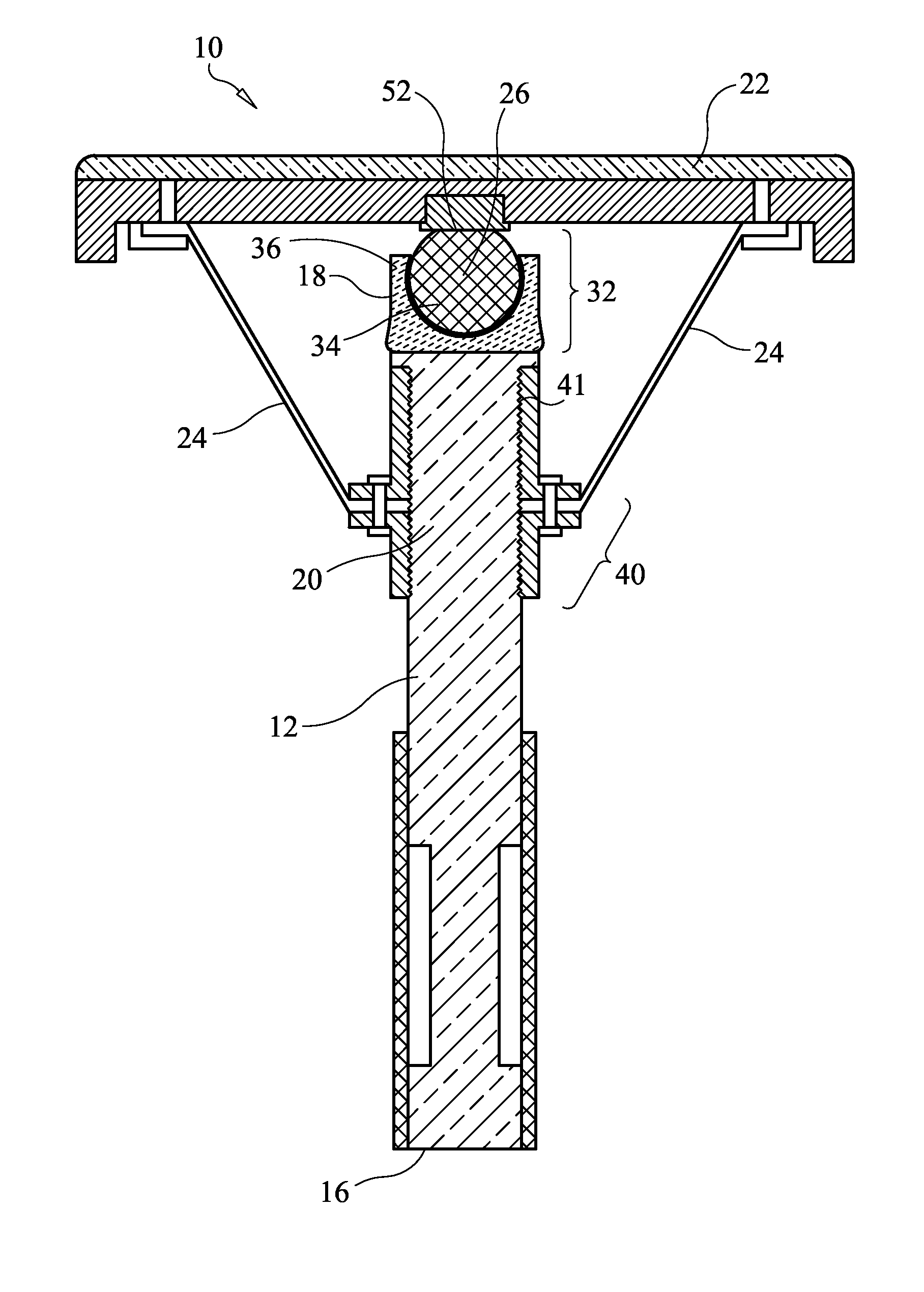
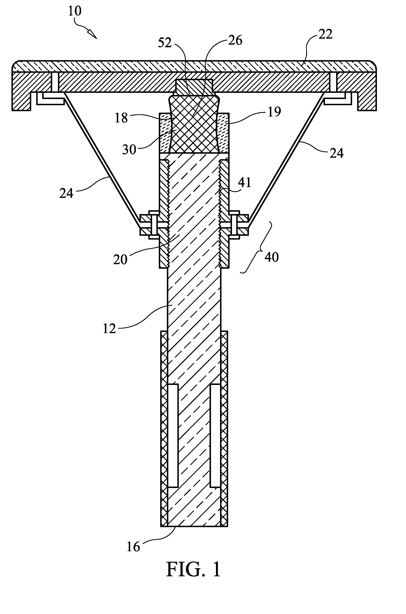
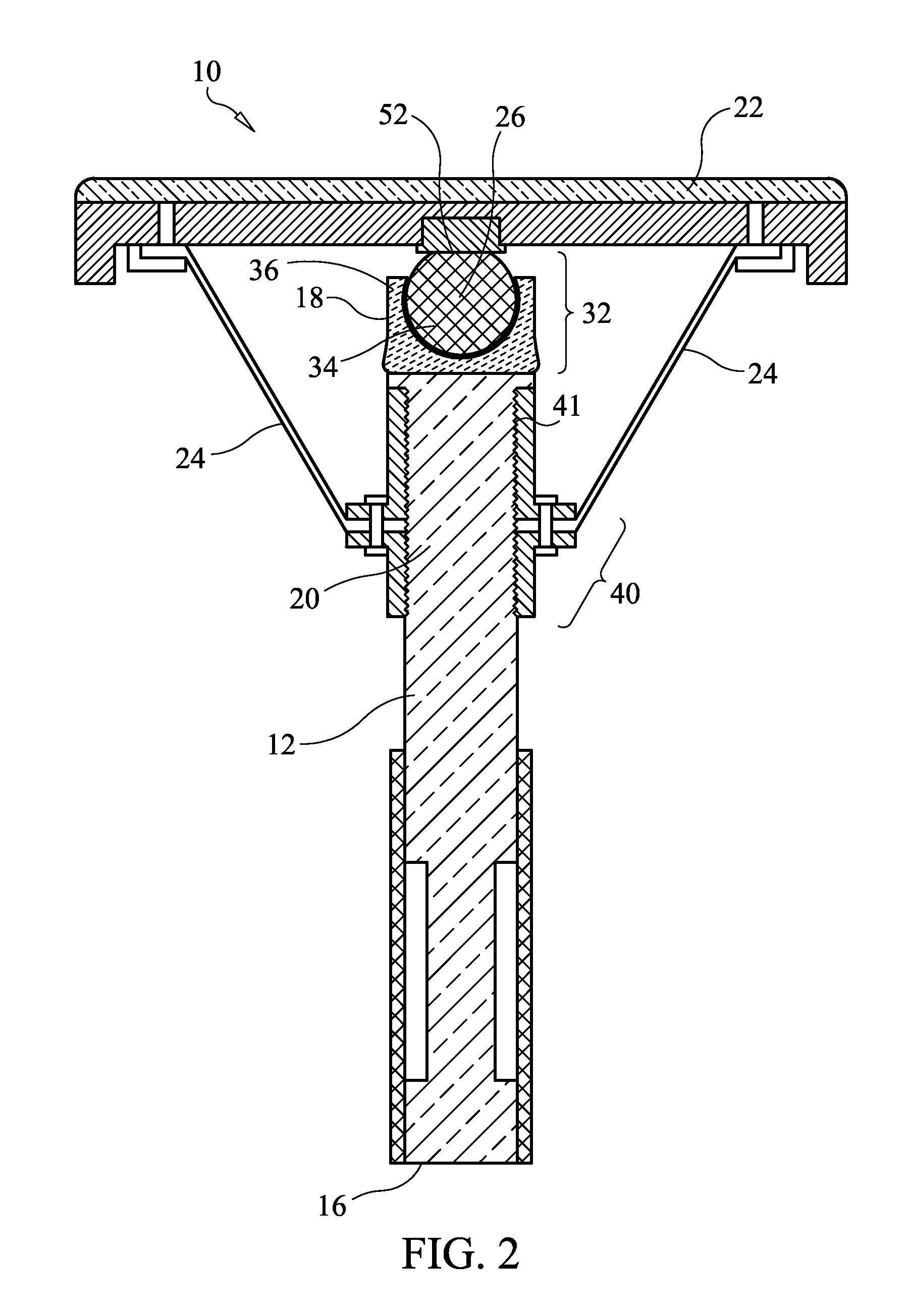
[0039]Referring now to FIGS. 1-3, a balance chair 10 includes a central vertical post 12 with a base 14 attached at a lower end 16 of the central post 12; a flexible joint 18 attached at an upper end 20 of the central post 12; a seat 22 attached atop the flexible joint 18; and a plurality of resistance members 24 attached to the central post 12 and the seat 22, wherein the plurality of resistance members 24 are arranged around the central post 12 in a spaced-apart manner, wherein the flexible joint 18 supports the seat 22 and enables the seat 22 to pivot about an effective pivot point 26 defined by the flexible joint 18, and wherein the resistance members 24 resist but do not prevent pivoting of the seat 22 about the effective pivot point 26. The flexible joint 18 and the resistance members 24 co-act to support pivoting of the seat 22 both side-to-side and fo...


PUM


Abstract

A balance chair includes a central vertical post with a base attached at a lower end of the central post; a flexible joint attached at an upper end of the central post, a seat attached atop the flexible joint; and a plurality of resistance members attached to the central post and the seat, wherein the plurality of resistance members are arranged around the post in a spaced-apart manner, wherein the flexible joint supports the seat and enables the seat to pivot about an effective pivot point as defined by the shape and composition of the flexible joint, and wherein the resistance members resist but do not prevent pivoting of the seat about the effective pivot point. The flexible joint and the resistance members support pivoting of the seat both side-to-side and fore-and aft and any combination thereof. The resistance members limit a degree of pivoting of the seat.

Description

RELATED APPLICATIONS[0001]This application claims priority of the U.S. provisional application 61 / 486,873 which was filed on 17 May 2011, and which is fully incorporated herewith by reference.FIELD OF INVENTION[0002]This invention relates to chairs, and in particular to a balance chair having a seat which is connected to a base by a gimballing joint and a plurality of resistance members.BACKGROUND OF THE INVENTION[0003]Many have sought to realize the benefits of movable platform seating, including decreased stiffness and injury. Decades of patents show that inventors have been attempting to design a chair which will bring the healthful benefits of dynamic seating to the public. If market success is the measure, no one has yet succeeded. In a ‘normal’ seating arrangement the chair is mostly stationary and the body rests upon it. In most movable platform seats, this relationship remains largely the same: though the platform is movable, the relationship between body and chair is still ...

Claims


Application Information

Patent Timeline
Patent Type & Authority Applications(United States)
IPC IPC(8): A47C3/00A47C7/40A47C7/54A47C3/20
CPCA47C7/14A47C7/42A47C3/025A47C9/002A47C3/0252A47C7/546A47C7/441A47C7/443A47C7/445A47C7/446A47C7/448
Inventor LEE, REBECCA M.
Owner LEE REBECCA M
Learn More