Lighting device, display device and television receiver

a technology of display device and lighting device, which is applied in the field of lighting device, display device and television receiver, can solve the problems of reducing the light emission efficiency of leds or their thermal degradation, and achieve the effect of improving the ability to dissipate heat generated by the light source in an edge light type lighting devi

Inactive Publication Date: 2012-11-22
SHARP KK
View PDF3 Cites 13 Cited by
  • Summary
  • Abstract
  • Description
  • Claims
  • Application Information

AI Technical Summary

Benefits of technology

[0021]According to the present invention, the capability of dissipating heat gen

Problems solved by technology

Thus, the temperature around the LEDs tends to increase, resulting in a decrease i

Method used


Image

  • Lighting device, display device and television receiver
  • Lighting device, display device and television receiver
  • Lighting device, display device and television receiver

Examples


first embodiment

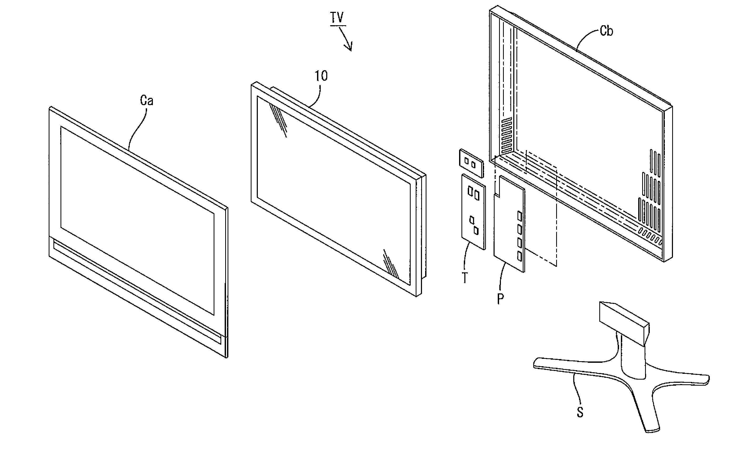
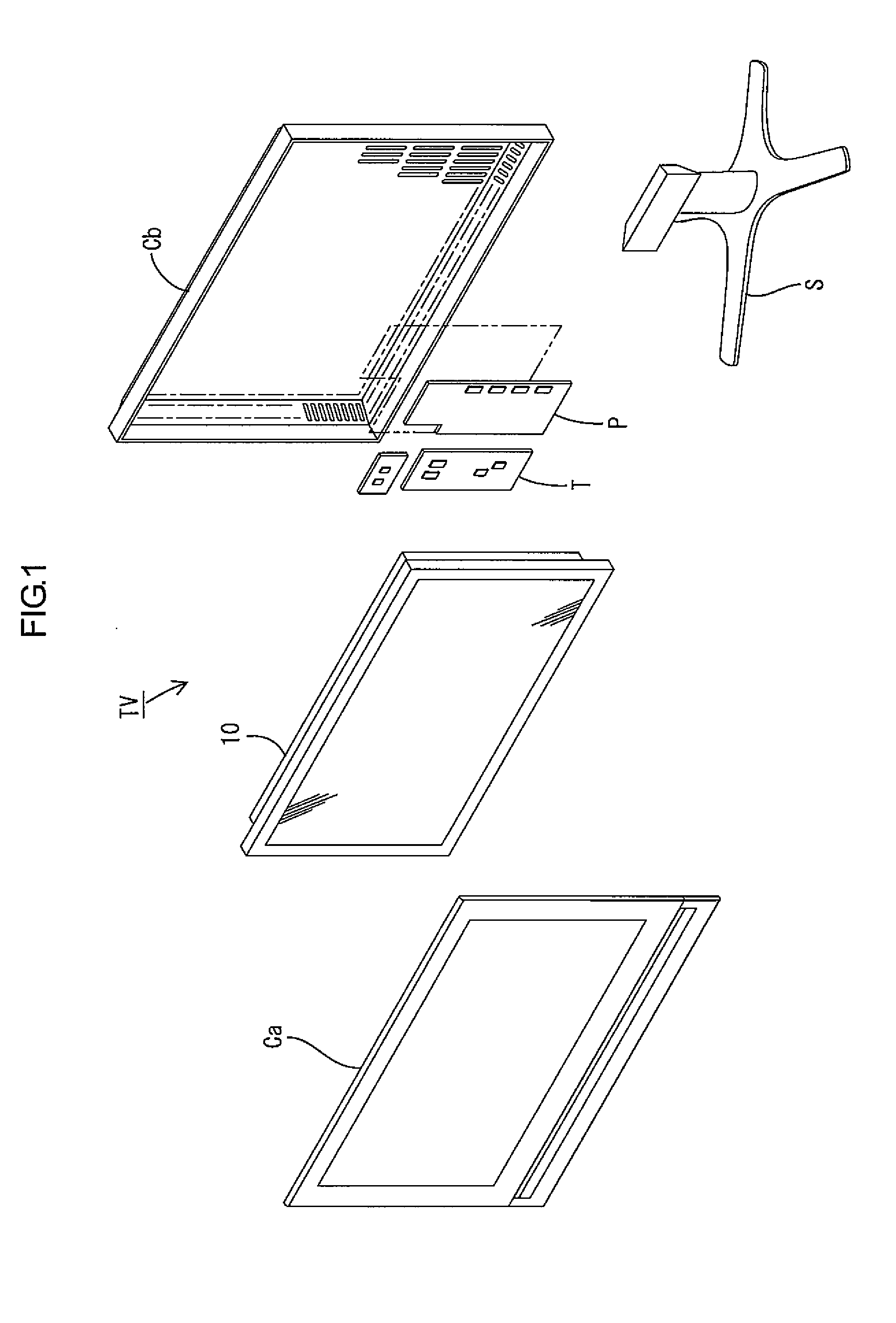
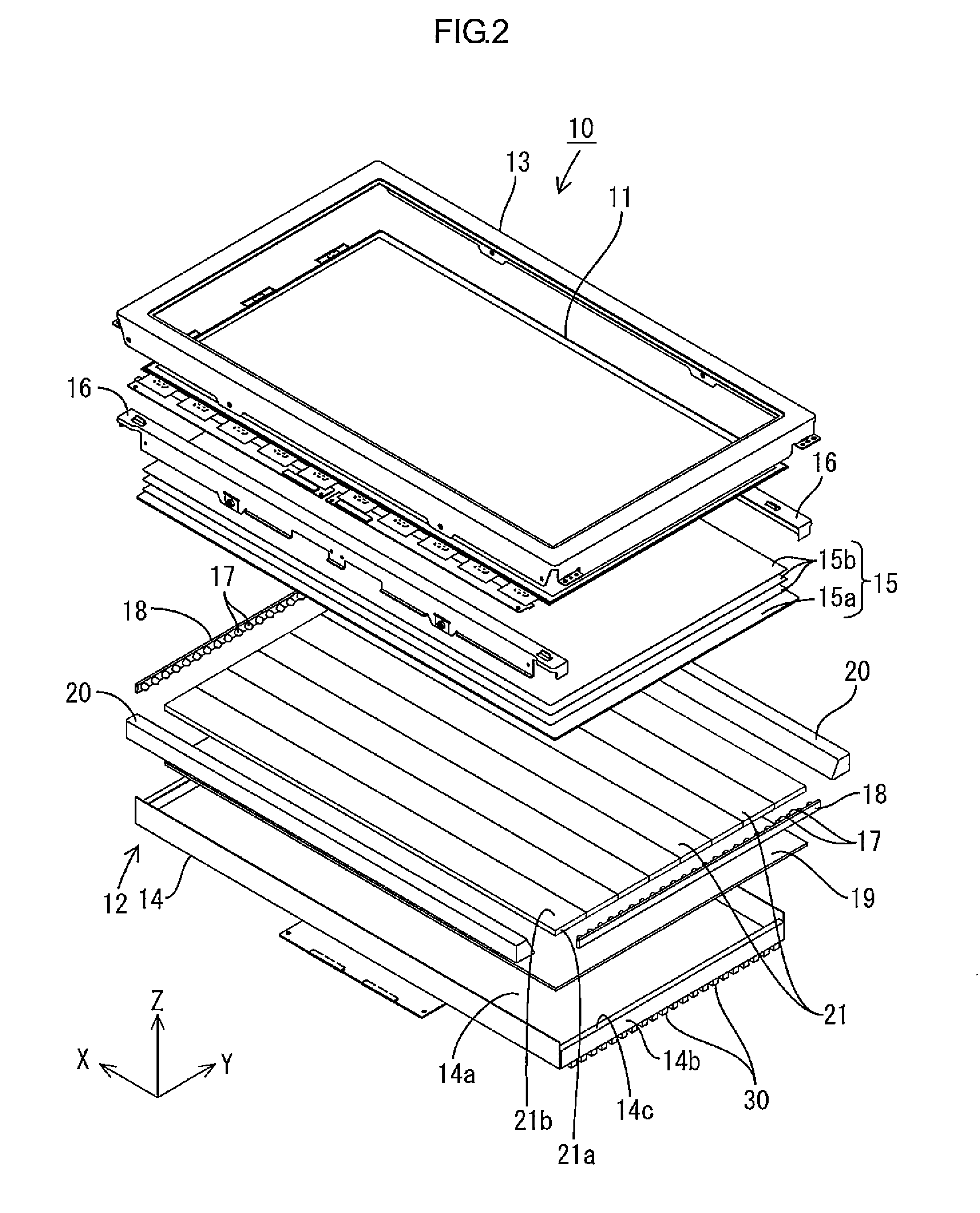
[0028]A first embodiment of the present invention will be described with reference to FIGS. 1 to 5. According to the present embodiment, a liquid crystal display device 10 will be described by way of example. FIG. 1 is an exploded perspective view illustrating a schematic configuration of a television receiver according to the present embodiment. FIG. 2 is an exploded perspective view illustrating a schematic configuration of the liquid crystal display device. FIG. 3 is a cross sectional view illustrating a cross sectional configuration of the liquid crystal display device along a short side direction thereof. FIG. 4 is a cross sectional view illustrating a cross sectional configuration of the liquid crystal display device along a long side direction thereof. FIG. 5 is a plan view of a back surface side of the liquid crystal display device. In some of the drawings, an X-axis, a Y-axis, and / or a Z-axis are shown. The directions of the axes are common throughout the drawings. An upper...

second embodiment

[0058]Next, a second embodiment of the present invention will be described with reference to FIG. 6.

[0059]The present embodiment differs from the first embodiment in that a heatsink 40 is connected to the LED boards 18, and the heat absorbing portions 31a of the heat pipes 30 are connected to the heatsink 40. The present embodiment is similar to the first embodiment in other respects and repetitive description will be omitted. FIG. 6 is an enlarged cross sectional view around the LEDs 17 illustrating a cross sectional configuration of the liquid crystal display device 10 taken along the short side direction.

[0060]As illustrated in FIG. 6, the heatsink 40 is connected to the surface of the LED boards 18 opposite to the LED 17 mounting surface. The heatsink 40 is a plate member of a metal with high heat conductivity. One plate surface of the heatsink 40 is fixed in contact with the LED boards 18. To the other surface, the heat absorbing portions 31a of the heat pipes 30 are affixed wi...


PUM


Abstract

A property of dissipating heat generated from a light source in an edge light type lighting device is improved. A lighting device includes: a plurality of LEDs 17; a chassis 14 housing the LEDs 17; light guide members 21 housed in the chassis 14 and including light entrance surfaces 21a through which light from the LEDs 17 enters and light output surfaces 21b from which the light exits; and a plurality of heat pipes 30 fixed on the chassis 14. The chassis 14 has a substantially rectangular bottom plate, and the LEDs 17 are arranged in a line on at least one of short sides of a bottom plate 14a of the chassis 14. The heat pipes 30 are formed in an elongated shape having one end that overlaps the LEDs 17 and another end that is provided on a middle portion of the chassis 14 in a longitudinal direction thereof.

Description

TECHNICAL FIELD[0001]The present invention relates to a lighting device, a display device, and a television receiver.BACKGROUND ART[0002]In recent years, display elements of an image display device, such as a television receiver, have been shifted from the conventional cathode-ray tube to thin display panels, such as liquid crystal panels or plasma display panels. This enables the image display device to have a reduced thickness. A liquid crystal panel does not emit light, and therefore a backlight unit is required as a separate lighting device. The backlight unit is provided on a back side (opposite side to a display surface) of the display panel and includes a metal chassis having an opening on a display panel side surface and a light source housed in the chassis.[0003]As a means of making the backlight unit thinner, an edge light type backlight unit is known. In the edge light type, the light source is disposed on a peripheral portion of the chassis. The light from the light sour...

Claims


Application Information

Patent Timeline
IPC IPC(8): H04N5/44F21V29/00G02F1/13357F21V8/00
CPCG02B6/0068G02B6/0073H05K7/2099G02B6/0085G02B6/0078
Inventor NEGORO, KAZUHIKO
Owner SHARP KK
Why Eureka
Try Eureka