
LED lamp and LED holder cap thereof

a technology of led lamps and led holders, which is applied in the direction of electric lighting, lighting and heating apparatus, lighting support devices, etc., can solve the problems of lowering the durability of conventional led lamps and insufficient soldering strength, and achieves stable and durable, low cost, and low soldering strength.

Inactive Publication Date: 2012-11-22
LIN CHIU MIN
View PDF6 Cites 96 Cited by
  • Summary
  • Abstract
  • Description
  • Claims
  • Application Information

AI Technical Summary

Benefits of technology

[0011]With the two parallel holding walls formed inside the LED holder cap of the lamp tube, the conducting holding walls can be directly connected with the power contacts of the circuit board of the lamp board after the LED holder caps are mounted around both ends of the hollow lamp tube, thereby avoiding the use of additional wires connected with the power contacts and the pins of the circuit board, cold solder, insufficient soldering strength and lower durability of the LED lamp. Accordingly, a more stable and durable LED lamp in accordance with the present invention can be provided.

Problems solved by technology

However, drawbacks such as cold solder or insufficient soldering strength may occur at solder joints and easily lead to loose contact between the LED holder cap and the connected power wire, thereby lowering the durability of the conventional LED lamps.

Method used


Image

  • LED lamp and LED holder cap thereof
  • LED lamp and LED holder cap thereof
  • LED lamp and LED holder cap thereof

Examples


Embodiment Construction

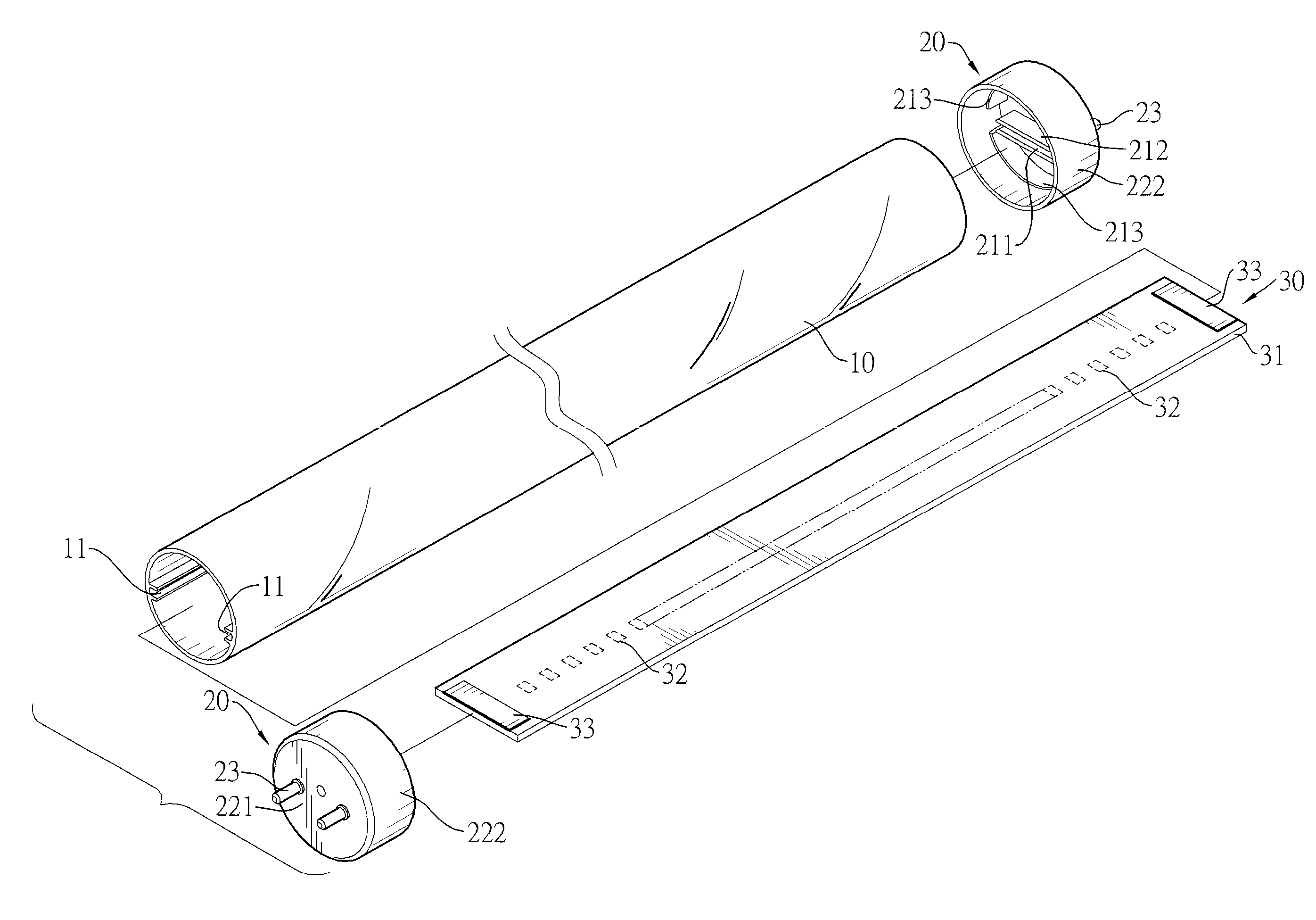
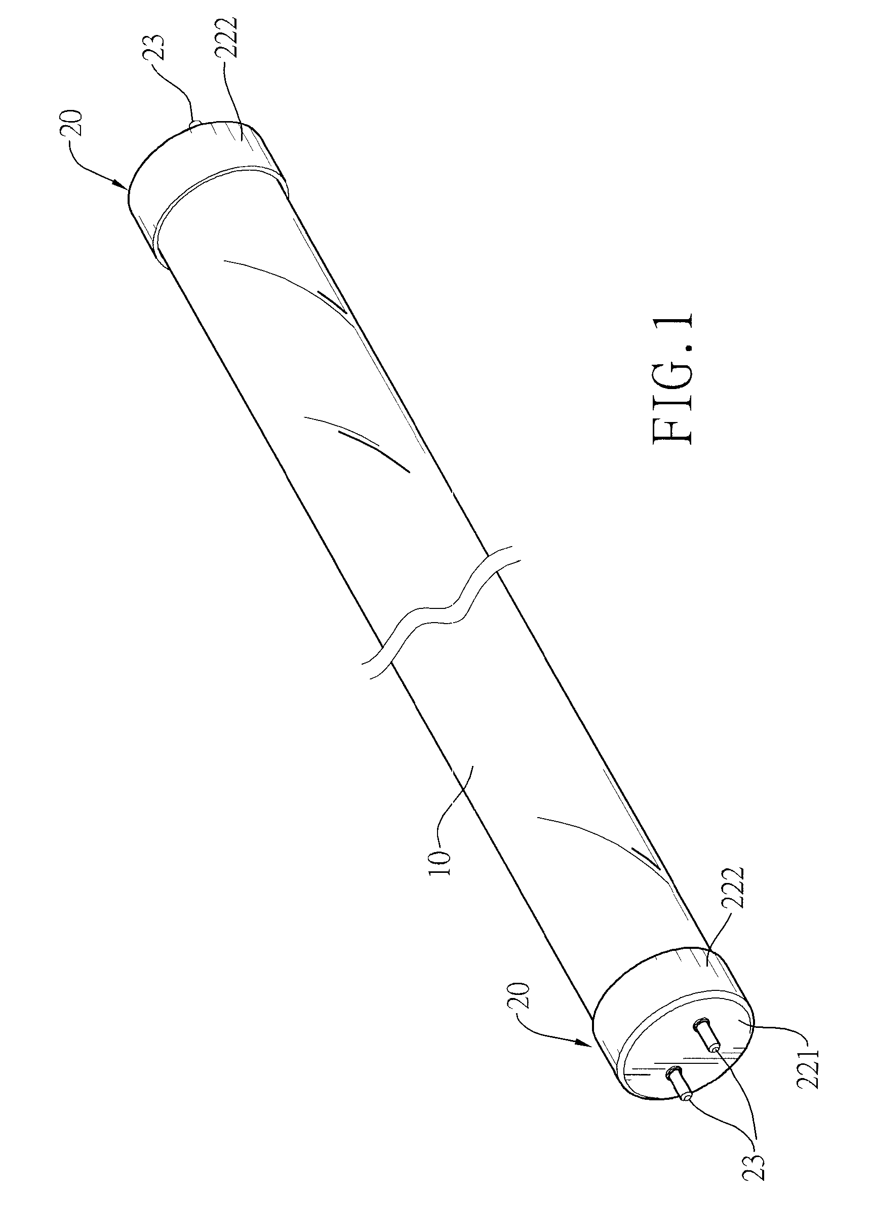
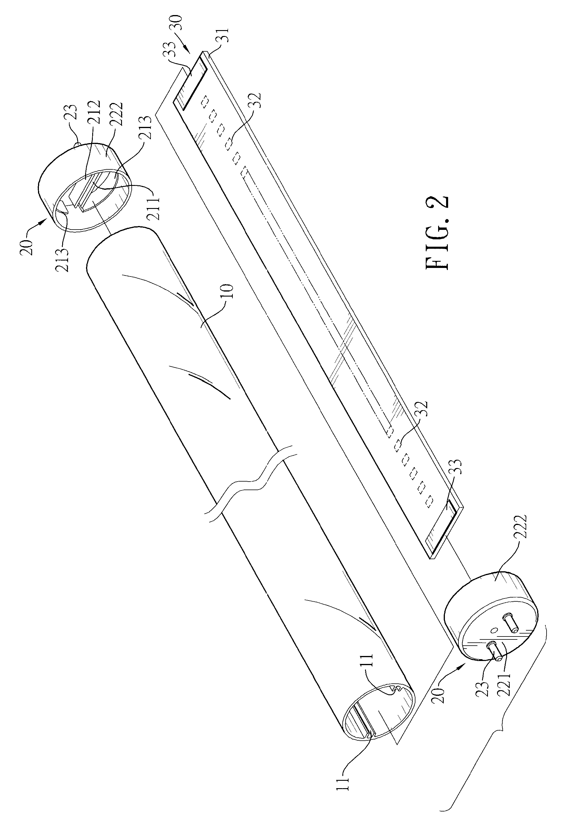
[0020]With reference to FIGS. 1 and 2, an LED lamp in accordance with the present invention has a hollow lamp tube 10, an LED lamp board 30 and two LED holder caps 20.

[0021]The lamp tube 10 has two openings formed through two ends of the lamp tube 10 and being opposite to each other. In the present embodiment, two sliding channels 11 are diametrically opposed and formed in an inner wall of the lamp tube 10.

[0022]The LED lamp board 30 has a circuit board 31, multiple LED light sources 32 and two power contacts 33. The circuit board 31 is mounted in the lamp tube 10 and is held in the two sliding channels 11. The LED light sources 32 are mounted on the circuit board 31. The power contacts 33 are respectively mounted on two ends of the circuit board 31 adjacent to the openings of the lamp tube 10. In the present embodiment, the LED light sources 32 are mounted on a bottom of the circuit board 31, and each power contact 33 is mounted on a top of one end of the circuit board 31 adjacent ...


PUM


Abstract

An LED lamp has an LED lamp board mounted in a lamp tube and two LED holder caps respectively mounted around two ends of the lamp tube. Each LED holder cap has a cap body, two pins and two parallel holding walls. One end of each pin is mounted in the circular board. One of the holding walls is conductive and connected with the pins. When the LED holder caps are respectively mounted around two ends of the lamp tube, the holding walls of each LED holder cap holds one end of the LED lamp board, and the conducting holding wall is electrically connected with a corresponding power contact of the LED lamp board so that the pins are respectively electrically connected with the power contacts. Accordingly, the problem of soldering wires with the LED lamp board and the pins of the LED holder caps can be eliminated.

Description

BACKGROUND OF THE INVENTION[0001]1. Field of the Invention[0002]The present invention relates to an LED lamp and LED holder cap, and more particularly to an LED lamp directly and electrically connected with a lamp board inside the LED lamp and an LED holder cap for the LED lamp.[0003]2. Description of the Related Art[0004]LED lamps are advantageous in energy conservation and environmental protection because of low power consumption and high light-emitting efficiency. As a result, LED lamps come into play to gradually replace conventional lamps recently. To avoid replacing a lamp socket due to incompatibility with an inserted LED lamp, the LED lamp is designed to be identical to the conventional incandescent bulb or fluorescent bulb in terms of size and electrical connection structure. One type of common LED lamps that is similar to conventional fluorescent lamps in size emerges to replace the conventional fluorescent lamps, and such an LED lamp has a lamp tube, an LED lamp board and...

Claims


Application Information

Patent Timeline
IPC IPC(8): F21S4/00F21V21/00
CPCF21K9/175F21Y2101/02F21Y2103/003F21Y2103/10F21Y2115/10F21K9/272
Inventor LIN, CHIU-MIN
Owner LIN CHIU MIN
Learn More