LED illumination apparatus and manufacturing method thereof

a technology of led street lamps and manufacturing methods, which is applied in the direction of lighting and heating apparatus, lighting support devices, fixed installations, etc., can solve the problems of increasing the manufacturing cost of led street lamps b>10/b>, the basic limitation of the related art structure on improving heat radiation efficiency, and the increase of the manufacturing cost of led street lamps. , to achieve the effect of reducing the heat radiation efficiency of led street lamps, and remarkably reducing the manufacturing cost of led street lamps

Inactive Publication Date: 2012-11-22
V L SYST
View PDF5 Cites 4 Cited by
  • Summary
  • Abstract
  • Description
  • Claims
  • Application Information

AI Technical Summary

Benefits of technology

[0021]According to the present invention, since a heat sink is formed on a rear surface of a body, reduction of heat radiation efficiency of an LED illumination apparatus due to dust or excrement of birds and the like is minimized.
[0022]In addition, since a body is formed though an extrusion molding, manufacturing cost of an LED illumination apparatus is remarkably reduced as compared with a related art die casting.
[0023]Further, since a length of a body is arbitrarily adjusted, an LED illumination apparatus can be designed to have various shapes according to a required heat radiation area.

Problems solved by technology

However, the related art LED streetlamp 10 has some problems as follows.
Since a periodic cleaning is inevitable to prevent the above mentioned problems, cost for maintenance management greatly increases.
Second, since an area of the heat sink 23 is restricted by a size of the body 20, the related art structure has a basic limitation on improvement of heat radiation efficiency.
In addition, when the body 20 is formed to have a large size for a sufficient heat radiation area, manufacturing cost of the LED streetlamp 10 excessively increases and the LED streetlamp 10 has excessive weight.
Third, since the body 20 of the related art LED streetlamp 10 is mostly formed through an aluminum die casting, manufacturing cost is excessively high.

Method used


Image

  • LED illumination apparatus and manufacturing method thereof
  • LED illumination apparatus and manufacturing method thereof
  • LED illumination apparatus and manufacturing method thereof

Examples


Embodiment Construction

[0032]Reference will now be made in detail to the preferred embodiments, examples of which are illustrated in the accompanying drawings.

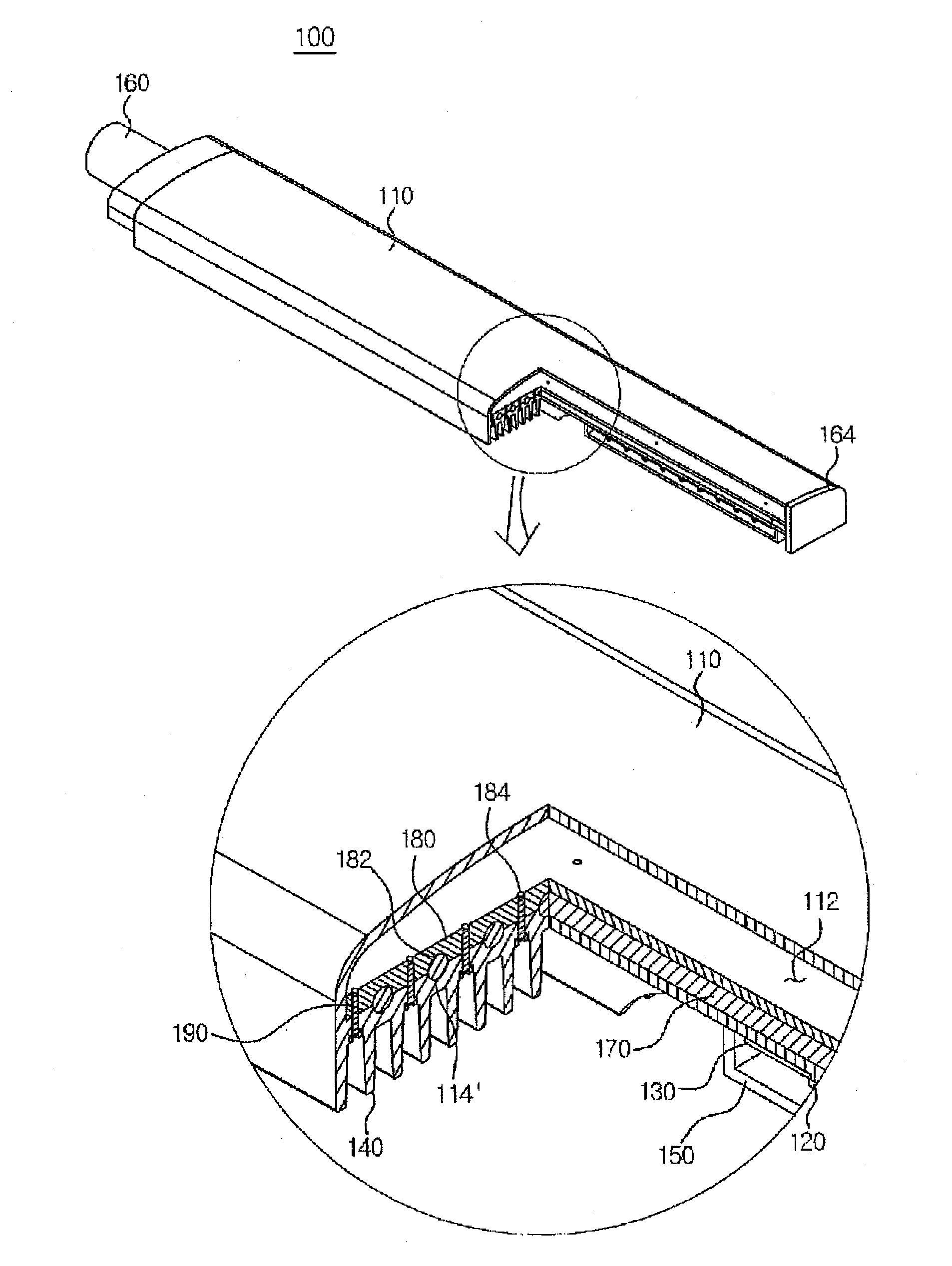
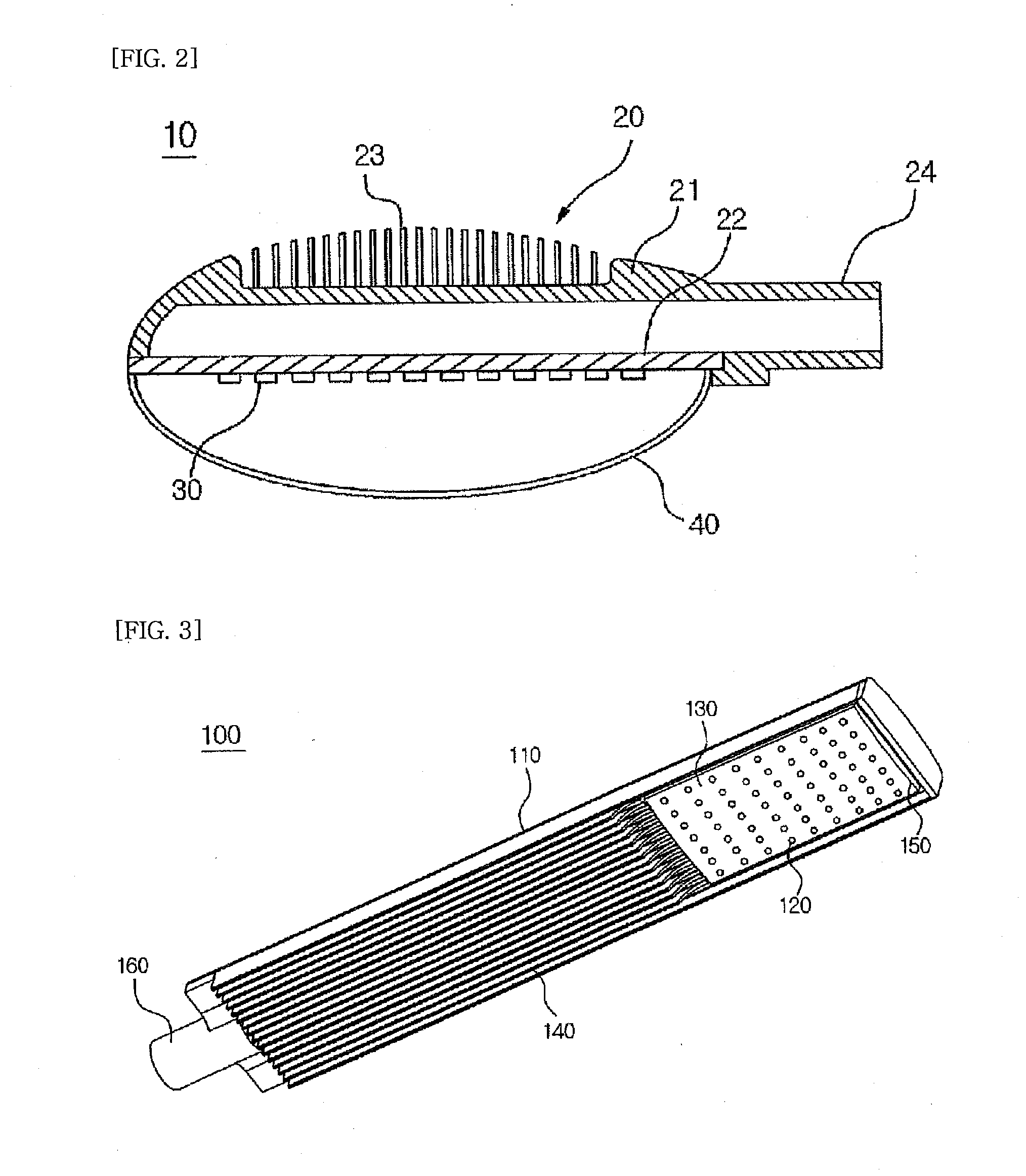
[0033]FIGS. 3 and 4 are a perspective view of a rear surface and a perspective view, respectively, showing an LED streetlamp 100 according to an embodiment of the present invention, FIGS. 5 and 6 are a partial cross-sectional view and a cross-sectional view, respectively, showing an LED streetlamp 100 according to an embodiment of the present invention, and FIG. 7 is an exploded perspective view showing an LED streetlamp 100 according to an embodiment of the present invention.

[0034]An LED streetlamp 100 according to an embodiment of the present invention includes a body 110 having a heat sink 140 of a heat radiation fin shape in a first region of a rear surface portion (a portion facing an illumination direction) thereof, an LED light source module 120 in a second region of the rear surface portion of the body 110 different from the first region and...


PUM

PropertyMeasurementUnit
areaaaaaaaaaaa
shrinkage fittingaaaaaaaaaa
electric energyaaaaaaaaaa

Abstract

The present invention relates to an LED illumination apparatus and a manufacturing method thereof. The LED illumination apparatus according to one embodiment of the present invention comprises: a body in which a heat sink including a plurality of heat radiation fins is formed in a first area of a bottom surface portion thereof and in which a light source loading area is formed in a second area different from the first area in the bottom surface portion; a substrate loaded on the light source loading area of the body; and an LED light source module provided on the substrate. According to the present invention, since the heat sink is formed in the bottom surface portion of the body, the reduction of heat radiation efficiency in the LED illumination apparatus due to dust or excrement of birds and the like can be minimized. In addition, since the body is manufactured by extrusion molding, the manufacturing cost of the LED illumination apparatus can be remarkably reduced in comparison with prior die casting. In addition, since the length of the body can be adjusted arbitrarily, the present invention can be designed in various shapes according to a desired heat radiation area.

Description

TECHNICAL FIELD[0001]The present invention relates to an LED (light emitting diode) illumination apparatus such as a streetlamp using an LED and a manufacturing method of the LED illumination apparatus, and more particularly, to an LED illumination apparatus where a heat sink that radiate a heat from an LED light source module is formed in a bottom surface portion of a body and is spaced apart from an LED light source portion along a longitudinal direction of the body.BACKGROUND ART[0002]An LED is a device that converts an electric energy into a light energy by recombination of minor carriers injected into a semiconductor having a PN junction structure.[0003]Recently, since the LED has a lower power consumption, a higher energy efficiency and a longer lifetime as compared with a related art fluorescent lamp and an incandescent lamp, utilization range of the LED has rapidly expanded around an indoor or outdoor illumination apparatus and an illumination apparatus for vehicle.[0004]In ...

Claims


Application Information

Patent Timeline
Patent Type & Authority Applications(United States)
IPC IPC(8): F21V29/00B23P15/26
CPCF21S8/086F21V29/004F21V29/006Y10T29/53113F21W2131/103F21Y2101/02F21V29/2212F21Y2115/10F21V29/74F21K9/00F21V29/51F21V29/713F21V29/763Y10S362/80F21K9/20F21S2/005
Inventor KIM, CHEOL-HYUNPARK, SUNG-CHUL
Owner V L SYST
Why Eureka
Try Eureka