Communication system, communication device, communication method, and processor
a communication system and communication method technology, applied in the field of communication systems, can solve problems such as the reduction in the flexibility of combinations of mobile station devices to be spatially multiplexed
- Summary
- Abstract
- Description
- Claims
- Application Information
AI Technical Summary
Benefits of technology
Problems solved by technology
Method used
Image
Examples
first embodiment
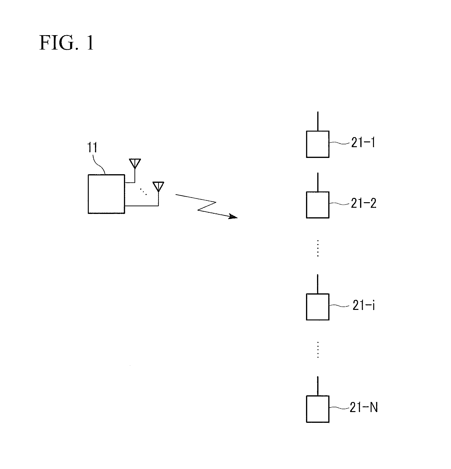
[0060]FIG. 1 is a schematic diagram illustrating a communication system according to a first embodiment of the present invention. This communication system includes one first communication device 11 and N second communication devices 21-1, . . . , 21-i, . . . , 21-N. Here, N is an integer equal to or greater than 2. The first communication device 11 includes N antennas and wirelessly communicates with the second communication devices 21-1, . . . , 21-i, . . . , 21-N. The second communication devices 21-1, . . . , 21-i, . . . , 21-N are collectively referred to as second communication devices 21 in some cases. This applies to explanations of other embodiments and modified examples. The first communication device 11 sends (transmits) spatially-divided N streams on which different data signals are superimposed. The second communication devices 21 receive (receive) these streams.
[0061]Each of the second communication devices 21 includes one antenna. A specific second communication devic...
second embodiment
[0162]Hereinafter, a second embodiment of the present invention is explained. First, a simple example is explained with reference to the drawings, and thereafter a generalized example is explained.
[0163]In FIG. 13, one base station device 13 wirelessly communicates with two mobile station devices 23-1 and 23-2. The base station device 13 includes four antennas 13-1, 13-2, 13-3, and 13-4. The mobile station device 23-1 includes antennas 23-1-1 and 23-1-2. The mobile station device 23-2 includes antennas 23-2-1 and 23-2-2. The mobile station device 23-1 is the aforementioned non-THP-compliant mobile station device. The mobile station device 23-2 is the aforementioned THP-compliant mobile station device. The antennas 13-1, . . . , 13-4 of the base station device 13 respectively transmit four streams on which different information data are superimposed. Two streams of the four streams are transmitted to the mobile station device 23-1. Other two streams of the four streams are transmitte...
third embodiment
[0217]Next, a third embodiment of the present invention is explained hereinafter.
[0218]In the third embodiment of the present invention, one base station device 14 and N mobile station devices 24 are provided. Here, N is an integer that is 2 or greater. The base station device 14 includes N antennas. The mobile station device 24 includes one antenna. The base station device 14 transmits spatially-divided N streams on which different data signals are superimposed. The mobile station device 24 receives these streams. Additionally, the base station device 14 can communicate with mobile station devices which are all non-THP-compliant in some cases, and can simultaneously communicate, by spatially multiplexing, with mobile station devices which are all THP-compliant in other cases.
[0219]FIG. 16 is a schematic block diagram illustrating a configuration of a primary transmission part of the base station device 14. The primary transmission part of the base station device 14 includes: modula...
PUM
 Abstract
Description
Claims
Application Information
 - R&D
- Intellectual Property
- Life Sciences
- Materials
- Tech Scout
- Unparalleled Data Quality
- Higher Quality Content
- 60% Fewer Hallucinations
Browse by: Latest US Patents, China's latest patents, Technical Efficacy Thesaurus, Application Domain, Technology Topic, Popular Technical Reports.
© 2025 PatSnap. All rights reserved.Legal|Privacy policy|Modern Slavery Act Transparency Statement|Sitemap|About US| Contact US: help@patsnap.com


