Image decoding device and image encoding device, methods therefor, programs thereof, integrated circuit, and transcoding device

a decoding device and image technology, applied in the field of image, to achieve the effect of increasing the decoding efficiency and coding efficiency, reducing the number of decoding units, and being easy to implemen

Inactive Publication Date: 2012-11-22
SOVEREIGN PEAK VENTURES LLC
View PDF6 Cites 14 Cited by
  • Summary
  • Abstract
  • Description
  • Claims
  • Application Information

AI Technical Summary

Benefits of technology

[0043]The image decoding device and the image coding device according to the present invention are capable of increasing the decoding efficiency and the coding efficiency and can be easily implemented. To be more specific, a plurality of decoding units or a plurality of coding units are connected via a memory, so that decoding or coding can be performed efficiently. This allows the number of decoding units or the number of coding units to be increased easily.

Problems solved by technology

This means that each of these image decoding and coding devices has to speed up the processing by increasing an operating frequency.

Method used


Image

  • Image decoding device and image encoding device, methods therefor, programs thereof, integrated circuit, and transcoding device
  • Image decoding device and image encoding device, methods therefor, programs thereof, integrated circuit, and transcoding device
  • Image decoding device and image encoding device, methods therefor, programs thereof, integrated circuit, and transcoding device

Examples


embodiment 1

[1-1. Overview]

[0101]Firstly, an overview of an image decoding device according to Embodiment 1 of the present invention is described.

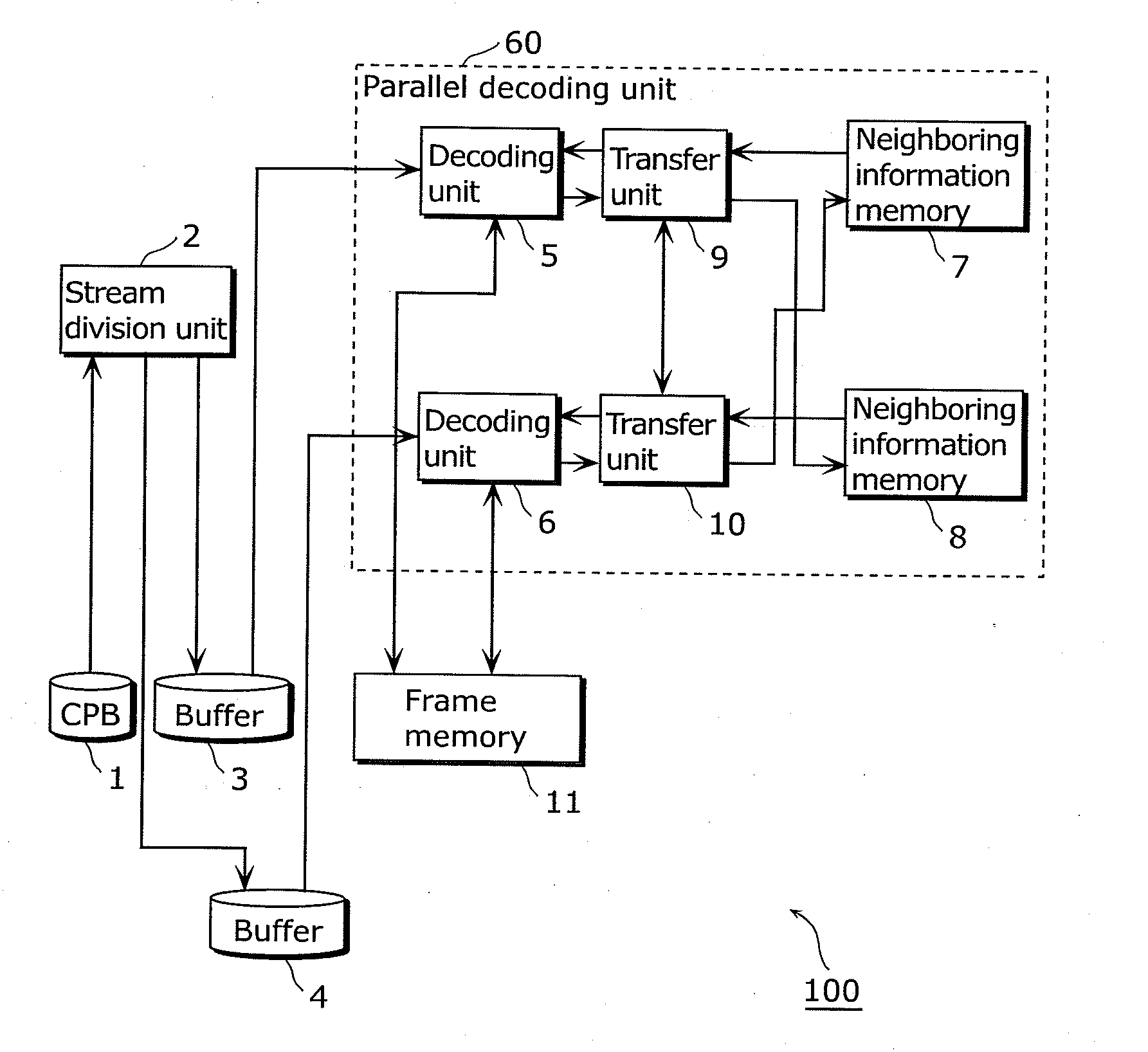
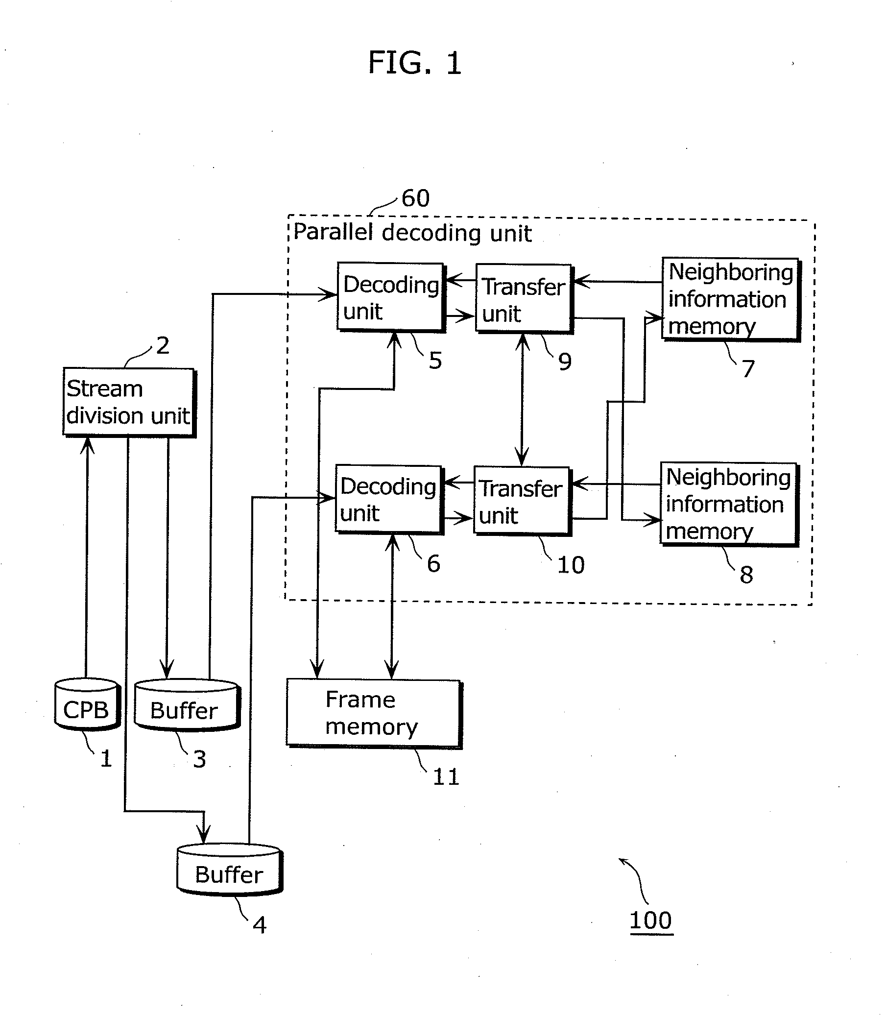
[0102]In the image decoding device in Embodiment 1, a stream division unit reads a coded stream generated as a result of coding an image, divides the coded stream so that two decoding units can perform decoding in parallel, and then stores the two divided streams generated as a result of the division into two buffers, respectively. Each of the two decoding units reads the divided stream stored in the buffer and decodes the read divided stream. Here, the decoding units decode the divided streams in synchronization with each other, by reference to each other's partial decoding result via a neighboring information memory.

[1-2. Configuration]

[0103]Next, a configuration of the image decoding device according to Embodiment 1 is described.

[0104]FIG. 1 is a block diagram showing the configuration of the image decoding device according to Embodiment 1.

[0105]An...

embodiment 2

[2-1. Overview]

[0192]Firstly, an overview of an image decoding device according to Embodiment 2 of the present invention is described.

[0193]In the image decoding device in Embodiment 2, a coded stream is divided into four, and four decoding units decode, in parallel, the four divided streams generated as a result of the division. Each of the four decoding units reads the divided stream stored in a buffer and then decodes the read divided stream. Here, each of the four decoding units decodes the divided stream in synchronization with another decoding unit, by reference to a partial decoding result given by the other decoding unit via a neighboring information memory.

[2-2. Configuration]

[0194]Next, a configuration of the image decoding device according to Embodiment 2 is described.

[0195]FIG. 20 is a block diagram showing the configuration of the image decoding device according to Embodiment 2. Components identical to those described in Embodiment 1 are assigned the same reference sign...

embodiment 3

[3-1. Overview]

[0210]Firstly, an overview of an image decoding device according to Embodiment 3 of the present invention is described.

[0211]The image decoding device in Embodiment 3 includes switches for switching data to be inputted into a decoding unit and a neighboring information memory. By the data switching executed by these switches, the image decoding device in Embodiment 3 switches between: a process where two decoding units decode one coded stream in synchronization with each other; and a process where the two decoding units independently decode two coded streams respectively.

[3-2. Configuration]

[0212]Next, a configuration of the image decoding device according to Embodiment 3 is described.

[0213]FIG. 22 is a block diagram showing the configuration of the image decoding device according to Embodiment 3. Components identical to those described in Embodiment 1 are assigned the same reference signs used in Embodiment 1 and are not explained again here.

[0214]An image decoding d...


PUM


Abstract

An image decoding device which increases decoding efficiency and can be easily implemented includes: a division unit dividing coded image data into first and second coded image data; a frame storage unit; first and second decoding units decoding, in parallel, the first and second coded image data; and an information storage unit. The first decoding unit decodes the first coded image data using second decoding result information stored in the information storage unit and stores, as first decoding result information, a part of information generated by the decoding into the information storage unit. The second decoding unit decodes the second coded image data using the first decoding result information stored in the information storage unit and stores, as the second decoding result information, a part of information generated by the decoding into the information storage unit.

Description

TECHNICAL FIELD[0001]The present invention relates to image decoding devices that decode coded images, image coding devices that code images, and so forth. In particular, the present invention relates to an image decoding device that performs parallel decoding, an image coding device that performs parallel coding, and so forth.BACKGROUND ART[0002]A conventional image coding device for coding a video sequence divides each picture included in the video sequence into macroblocks, and performs coding for each of the macroblocks. The size of a macroblock is 16 pixels high and 16 pixels wide. Then, the conventional image coding device generates a coded stream, that is, a coded video sequence. After this, a conventional image decoding device decodes this coded stream on a macroblock-by-macroblock basis to reproduce the pictures of the original video sequence.[0003]The conventional coding methods include the International Telecommunication Union Telecommunication Standardization Sector (ITU...

Claims


Application Information

Patent Timeline
Patent Type & Authority Applications(United States)
IPC IPC(8): H04N7/12
CPCH04N19/50H04N19/593H04N19/16H04N19/44H04N19/82H04N19/436H04N19/00896H04N19/00224H04N19/00472H04N19/00521H04N19/00533H04N19/00569H04N19/00763H04N19/40
Inventor TANAKA, TAKESHIYOSHIMATSU, NAOKIKUROKAWA, KEIICHIIWAHASHI, DAISUKE
Owner SOVEREIGN PEAK VENTURES LLC
Why Eureka
Try Eureka