Style of Fan Device

a fan device and fan body technology, applied in the direction of machines/engines, stators, liquid fuel engines, etc., can solve the problems of insufficient wind strength, difficult to sell out, and poor outward appearance of little, so as to reduce costs, increase production, and increase consumer interest.

Inactive Publication Date: 2012-11-22
LEE PAO FENG
View PDF5 Cites 6 Cited by
  • Summary
  • Abstract
  • Description
  • Claims
  • Application Information

AI Technical Summary

Benefits of technology

[0023]In addition, with the match of a front cover (13) and a back cover (14), this device can cut down the cost and is easy to have large production for more consumers.
[0024]Moreover, said an inflow part (11) can be increased or changed with its position. On left and right sides of said back cover(14), on the top of a front cover (13) of an inflow part (11), there is a L shape positioning stand (15) of a groove (151) which set the position of a card holder (20). Through the use of a positioning stand (15), this fan can have more functions, that is to cool down with wind and have a place to set certificate. As it is mentioned above, said a centrifugal fan (2) is made of a motor (21) on the side of a cover (1) and a vane wheel (22) connected with a motor (21) in a cover (1). Through the device of this a motor (21) and a vane wheel (22), it can make a centrifugal fan (2) functions well and make the wind turned 90 degree to save space. There is a switch button (31) on the outer part of said switch (3); said switch (3) can work with a power supply unit (4) in the inner part and offers a positioning sheet (32) of a switch (3).
[0025]Through the use of a switch (3), it is easier for consumers to control a switch button (31) with a positioning sheet (32) to sustain. Said a power supply unit (4), inside a cover (1), is made of several battery cell (411) of a battery (10) inside a set of a battery cartridge (41), and a sprung conductive slice (421) with a battery cartridge cover (42); said a battery cartridge cover (42) has a uncinate conductor (422) to work with; said a battery cartridge (41) corresponds to a uncinate conductor (422) to work with a conductive slice (412). Through the use of a power supply unit (4), a conductive slice (412) work with a uncinate conductor (422) to make a battery cartridge (41) and a battery cartridge cover (42) work and make it easy for a battery cartridge cover (42) to open and close; in addition, this design can be free from the loss of a battery cartridge cover (42) when people are filling the battery. Said a power supply unit (4), inside the cover (1), is made up of several battery cell (411) of battery cartridge (41) with a battery (10) and a battery stand cover (43) connected with a battery cartridge (41) on the bottom of a cover (1). This device is suitable to different a cover (1) without any problem.
[0026]Said outflow part (12) has fan like a fan cover (6) to prevent from falling.
[0027]An outflow part (12) is close to the chest, neck and head of users so this design needs a more safety standard and provides more safety for users.

Problems solved by technology

The portable traditional tiny fan can make cool wind but there are still some problems here: The traditional fan worked with a drive unit but the wind is not strong enough.
In addition, its outward appearance is not good with little variety, so it is hard to sell out.

Method used


Image

  • Style of Fan Device
  • Style of Fan Device
  • Style of Fan Device

Examples


Embodiment Construction

[0011]The detailed descriptions of the drawings are as follows:

[0012]FIGS. 1, 3, and 5 shows the first to third embodiment of this invention, and FIGS. 2, 4, and 6 shows the first to third embodiment of this invention.

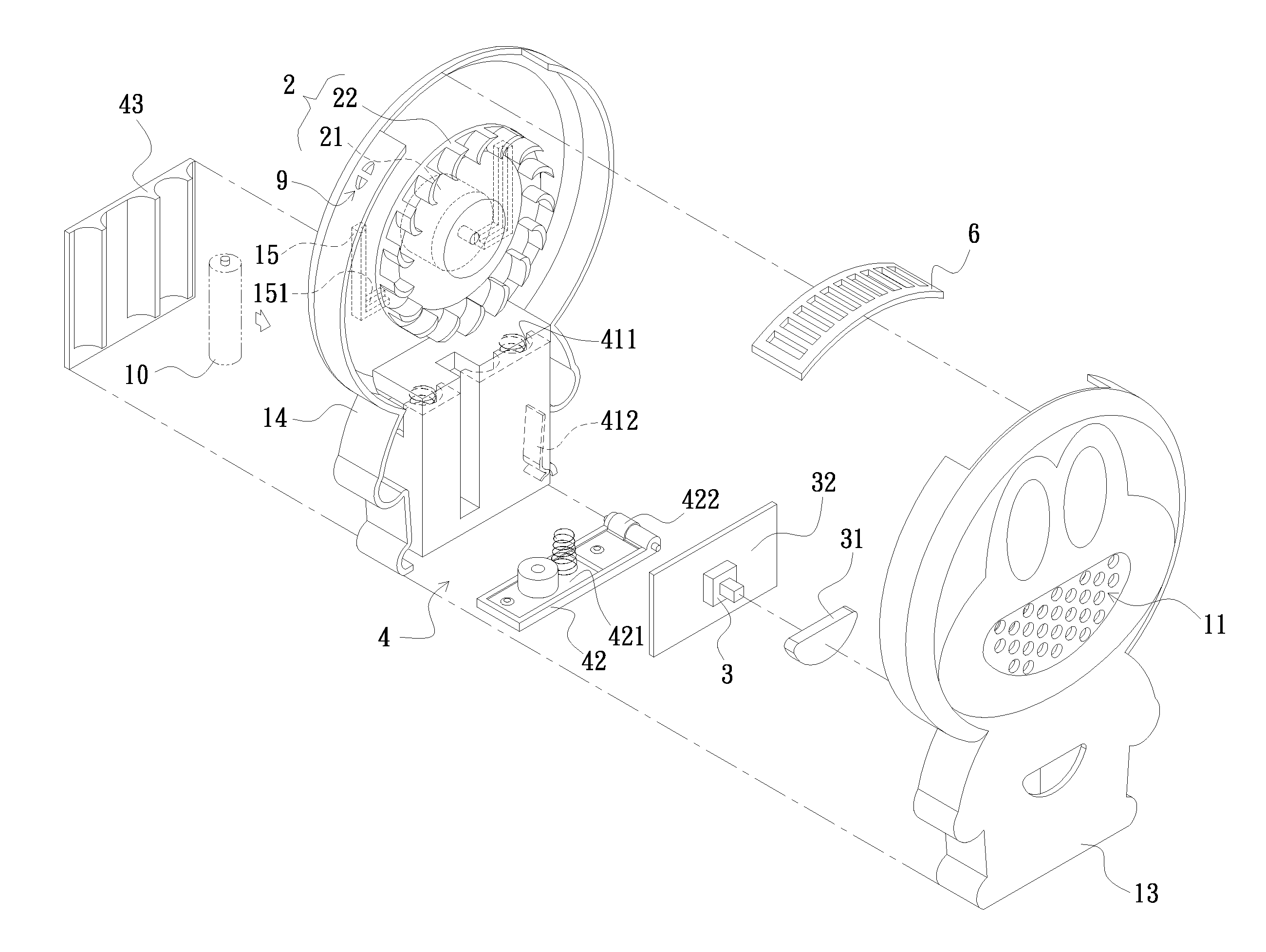
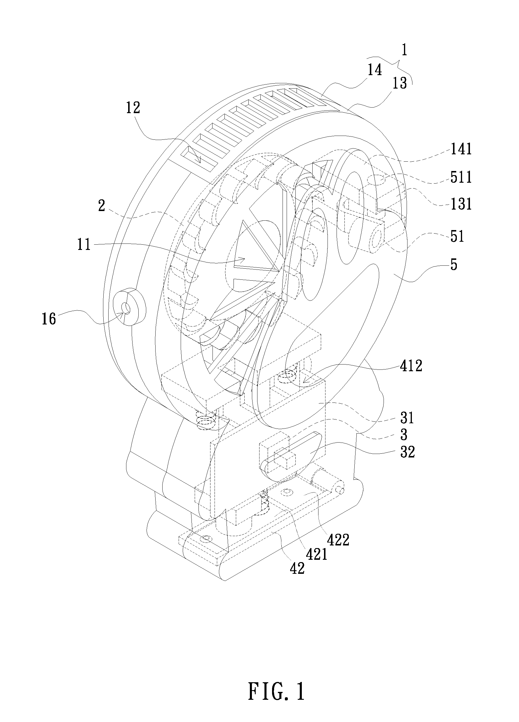
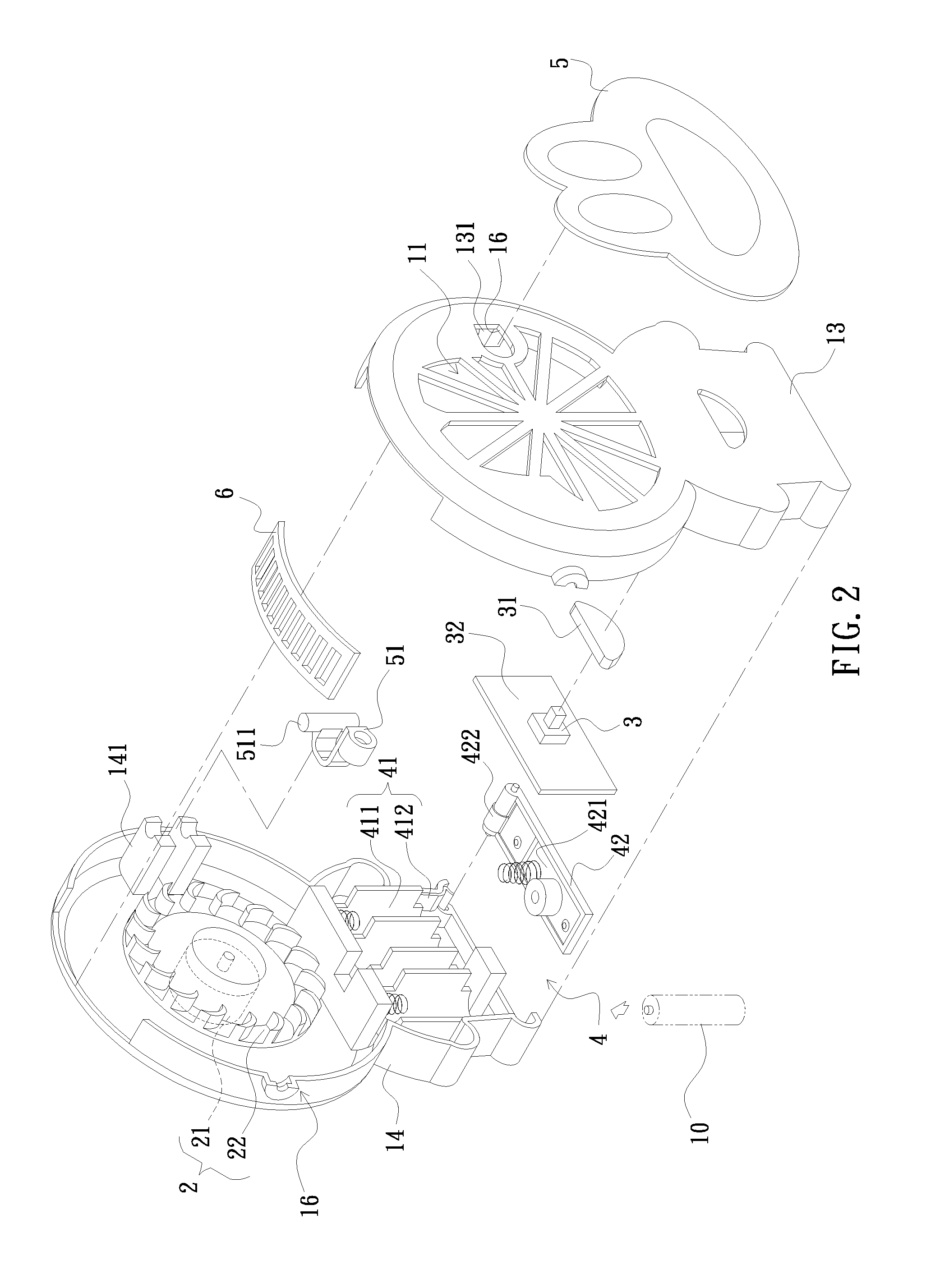
[0013]The fig. shows An Improved Style of Fan Device, which contains:

[0014]a hollow cover (1); a centrifugal fan (2) on the top of the cover (1); a switch (3), on the front of a cover (1), connected with a centrifugal fan (2); and a power supply unit (4), on the bottom of a cover (1), connected with a centrifugal fan (2) and a switch button (3); said cover (1) corresponds to a Air-Intake flow (I) of a centrifugal fan (2) contains at least an inflow part (11); and there are at least an outflow part (12) corresponds to Air-Outtake flow (T) of a centrifugal fan (2); said Air-Intake flow (I) and Air-Outtake flow (T) of a centrifugal fan (2) is vertically designed; it is characterized in that: a said inflow part (11) connected with a cover (1) and can control open and close...


PUM


Abstract

It is an improved style of fan device without much noise. The characters contain a hollow cover, a centrifugal fan, a switch, connected with the centrifugal fan, and a power supply, connected with centrifugal fan; there are at least one inflow part and one outflow part at least; said inflow and outflow fan is vertically designed; the improved style of fan device is characterized in that there is a fan cover in the inflow part area to open and close.

Description

REPRESENTATIVE DRAWINGS[0001]It is on chart 1.FIELD OF THE INVENTION[0002]This invention is involved with a style of fan.DESCRIPTION OF THE PRIOR ART[0003]The portable traditional tiny fan can make cool wind but there are still some problems here: The traditional fan worked with a drive unit but the wind is not strong enough. People have to take the traditional fan with hands because it is axial flow. In addition, its outward appearance is not good with little variety, so it is hard to sell out. Thus how to make a new style of fan good in quality, outward appearance and function is the main mission.SUMMARY OF THE INVENTION[0004]This invention is portable, safe, and in low noise. There are two methods to make this invention:First Method:[0005]An Improved Style of Fan Device includes a hollow cover (1); a centrifugal fan (2) on the top of the cover (1); a switch (3), on the front of cover (1), connected with the centrifugal fan (2); and a power supply unit (4),on the bottom of the cov...

Claims


Application Information

Patent Timeline
Patent Type & Authority Applications(United States)
IPC IPC(8): F01D1/02
CPCF04D29/703F04D25/08
Inventor LEE, PAO-FENG
Owner LEE PAO FENG
Why Eureka
Try Eureka