Intra-oral scanner

a scanner and intraoral technology, applied in the field of intraoral scanners, can solve the problems of difficulty in preservation, material consumption, and possibility of damage to prepared casts

Active Publication Date: 2012-11-22
THEO DENTAL
View PDF3 Cites 9 Cited by
  • Summary
  • Abstract
  • Description
  • Claims
  • Application Information

AI Technical Summary

Benefits of technology

[0009]With the above-described technical means of the illustrative embodiment, the intra-oral scanner is inserted into a patient's oral cavity to scan the patient's teeth in a contactless manner. Thus, three-dimensional data for the patient's teeth can be exactly measure

Problems solved by technology

However, in the impression taking process, there have been problems, e.g., consumption of materials, cross-infection, possibility of damage to prepared casts, and preservation difficulties.
However, since the conventional method depends on measurement through two-dimensional manual works using radiograp

Method used


Image

  • Intra-oral scanner
  • Intra-oral scanner
  • Intra-oral scanner

Examples


Embodiment Construction

[0018]Hereinafter, illustrative embodiments will be described in detail with reference to the accompanying drawings so that inventive concept may be readily implemented by those skilled in the art. However, it is to be noted that the present disclosure is not limited to the illustrative embodiments and can be realized in various other ways. In the drawings, certain parts not directly relevant to the descriptions of the present disclosure are omitted to enhance the clarity of the drawings. Throughout this document, like reference numerals denote like parts.

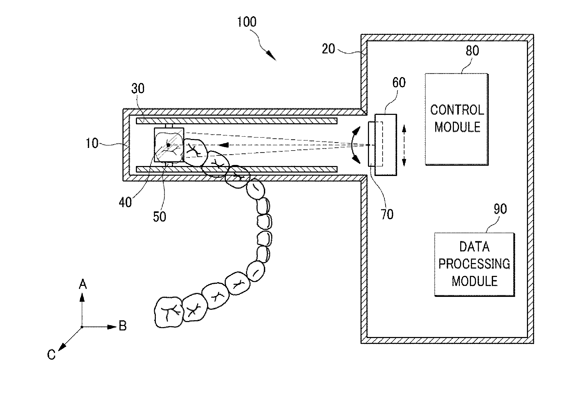
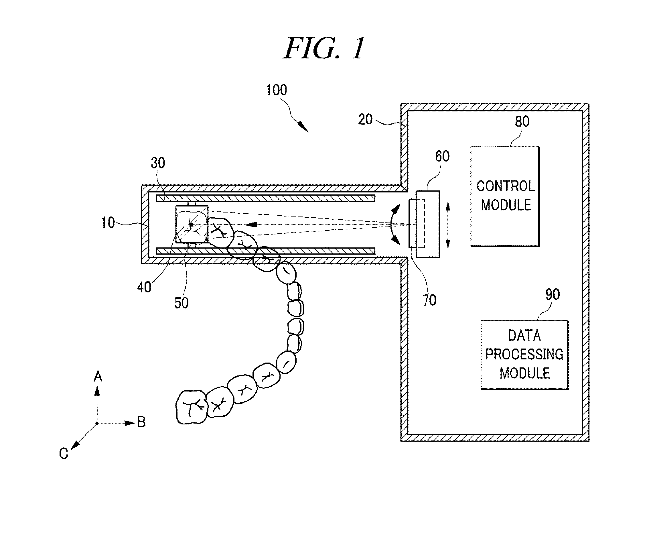
[0019]FIG. 1 is a plane view of an intra-oral scanner in accordance with an illustrative embodiment.

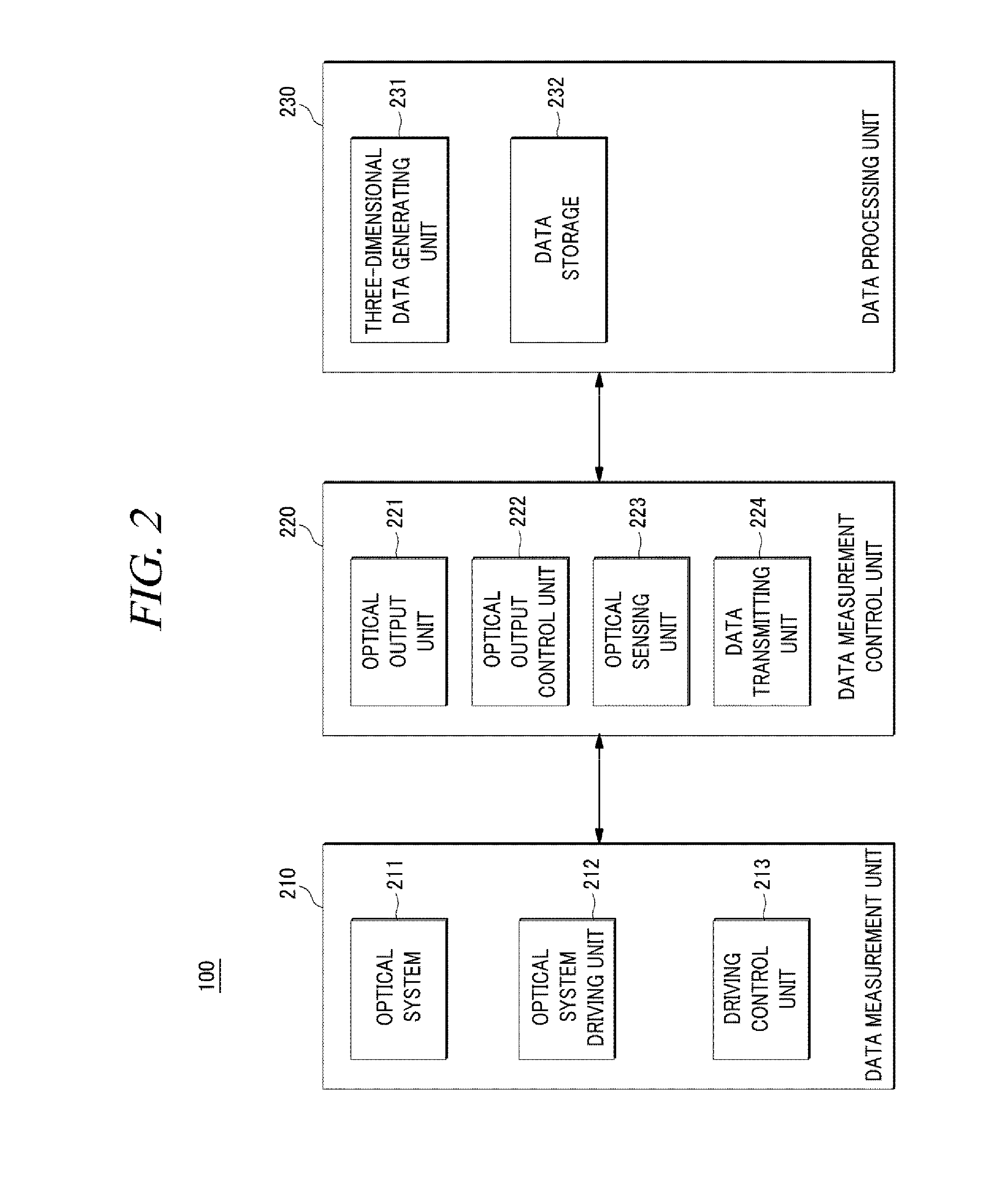
[0020]FIG. 2 is a block diagram showing configuration of an intra-oral scanner in accordance with an illustrative embodiment.

[0021]FIG. 3 is a side view of an intra-oral scanner in accordance with an illustrative embodiment.

[0022]As illustrated in FIGS. 1 and 3, an intra-oral scanner 100 in accordance with an illustrative embodiment ...


PUM


Abstract

An intra-oral scanner includes an optical output unit; an optical output control unit configured to rotate the optical output unit along a first reference axis or moves the optical output unit so as to control an emission position of the output light; an optical system configured to reflect the output light with the emission position controlled by the optical output control unit to a tooth or teeth being scanned; an optical system driving unit configured to rotate the optical system along a second reference axis so as to control a reflection angle of the output light; a guide; an optical sensing unit configured to sense the light reflected by the optical system and convert the sensed light into an electrical signal; and a data transmitting unit configured to transmit information to a three-dimensional data generating unit to generate three-dimensional scanning model for the tooth or teeth being scanned.

Description

TECHNICAL FIELD[0001]The present disclosure relates to an intra-oral scanner, in particular, to an intra-oral scanner, which is inserted into a patient's oral cavity to scan the patient's teeth.BACKGROUND ART[0002]In general, dental hospitals or the like have performed medical cures and treatments to patients' affected parts through impression taking that prepares plaster casts for the patients' teeth. However, in the impression taking process, there have been problems, e.g., consumption of materials, cross-infection, possibility of damage to prepared casts, and preservation difficulties.[0003]As a conventional method widely used to see the state of a patient's oral cavity, there has been a method of inserting a sheet-shaped film into the patient's oral cavity, fixing the film in the proximity of the patient's affected part by using the patient's hand or tongue, projecting a radiation ray such as an X-ray onto the affected part of the oral cavity, and using the film obtained from th...

Claims


Application Information

Patent Timeline
IPC IPC(8): A61B6/14
CPCA61B5/0062A61C9/0053A61B6/145A61B5/0088A61B5/0064A61B1/24A61B6/14
Inventor KIM, JIN HWAN
Owner THEO DENTAL
Why Eureka
Try Eureka