Micro needle and micro needle device

Inactive Publication Date: 2012-11-22
UBIOMED
View PDF4 Cites 25 Cited by
  • Summary
  • Abstract
  • Description
  • Claims
  • Application Information

AI Technical Summary

Benefits of technology

[0017]The micro needle according to the various embodiments attains the following effects.
[0018]According to the first embodiment, since the needle has a cross (+) shape, and a medication can be transferred into a skin. In addition, since the recesses are disposed only in the side wall of the needle, the strength of the needle can be ensured, to thereby prevent the needle from being broken within a skin when a medication is injected.
[0019]According to the second embodiment, since the needle includes the recess having a cross (+) shape, a certain volume of a medication is captured within the recess, and is injected into a skin. Thus, the medication captured within the recess can be effectively injected into the skin. In addition, since the recess is short within the straight part of the needle, the strength of the needle can be ensured, to thereby prevent the needle from being broken within a skin when a medication is injected.
[0020]According to the third embodiment, since the recess extending along the central portion of the needle has a larg

Problems solved by technology

However, when medications are transferred through an oral administration, operations of digestive enzymes within an alimentary canal may prevent the medications from being directly absorbed into a blood flow, or may modify the medications so as to jeopardize desired effects thereof.
However, a needle penetrates the dermis of the skin during the injection, which may cause pain or infection.
However, at this point, a large amount of the medication is blocked by the skin, and a very small amount of the medication is injected into the skin.
In addition, when hollow-type needles having a hollow part in the center thereof are used to inject a medication to a skin, they are susceptible to a breakage, and air from the hollow part may be introduced to the skin, before the injection.
Furthermore, typical micro needle apparatuses do not include a device for relaxing a skin having pores constricted at low temperature, or a hardened cell tissue.
As a result, injection efficiency of the medication may be degraded.
Furthermore, typical micro needle apparatuses do not have a dev

Method used


Image

  • Micro needle and micro needle device
  • Micro needle and micro needle device
  • Micro needle and micro needle device

Examples


first embodiment

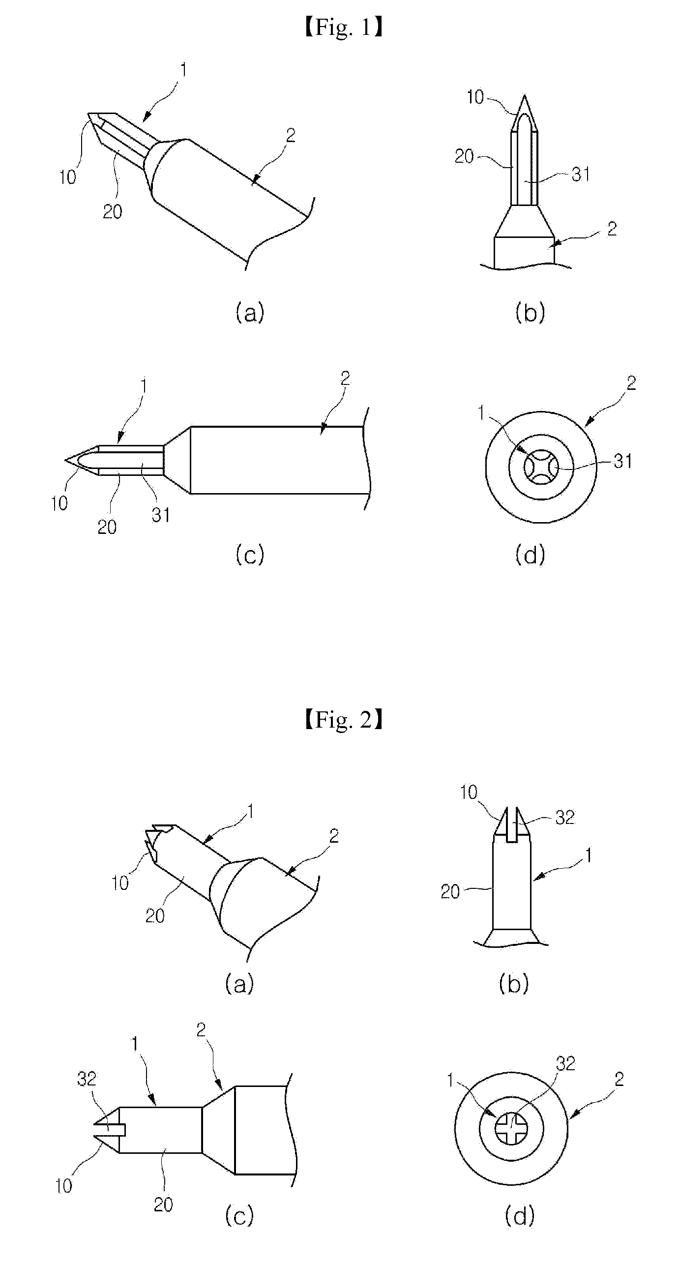
[0051]Referring to FIG. 1, a micro needle includes a needle 1 and a body 2.

[0052]The needle 1 penetrates a skin to inject a medication. The body 2 is coupled to the needle 1 to move or support the needle 1. A medication is transferred from the body 2 to the needle 1. The body 2 has an approximately cylindrical shape and a taper shape that decreases in diameter at a portion connecting to the needle 1 having a diameter smaller than that of the body 2.

[0053]The needle 1 includes: a straight part 20 having an end contacting the body 2, and including a straight outer wall; and an inclined part 10 extending outward from the other end of the straight part 20, and including an inclined outer wall with a sharp end decreasing in diameter.

[0054]Both the inclined part 10 and the straight part 20 may penetrate a skin, or only the inclined part 10 may penetrate a skin according to a user's need.

[0055]Recesses 31 having a straight line shape extending along the needle 1, and recessed a certain de...

fourth embodiment

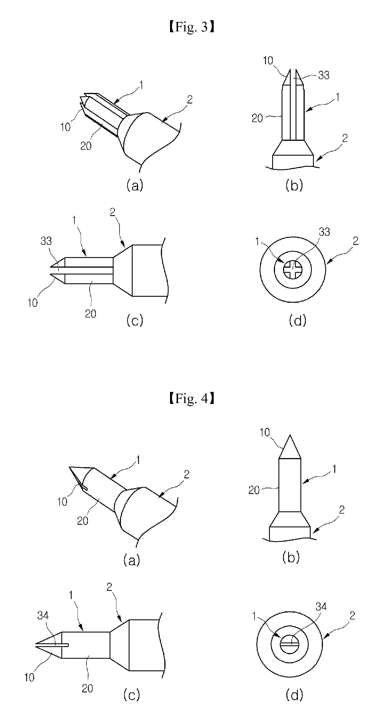
[0062]FIGS. 4A to 4D are views illustrating a micro needle according to a Referring to FIGS. 4A to 4D, a flat-shaped (−) recess 34 is recessed a certain depth toward a body 2 in the central portion of an inclined part 10 of a needle 1. The recess 34 may extend from an end of the inclined part 10 to a portion of a straight part 20 as illustrated in FIG. 4C, and have a flat (−) shape with two branches toward the left and right (or upper and lower) sides of the needle 1 as illustrated in FIG. 4D.

second embodiment

[0063]Since the recess 34 has a flat (−) shape as illustrated in FIGS. 4A to 4D, a certain volume of a medication is captured within the recess 34. In this state, when the needle 1 is inserted into a skin, the medication captured within the recess 34 is effectively injected into the skin. In addition, since the recess 34 has a short portion in the straight part 20 of the needle 1, and the branches of the recess 34 are fewer than those of the recess 33 of the second embodiment, the strength of the needle 1 can be increased, to thereby fundamentally prevent the needle 1 from being broken within a skin when a medication is injected.

[0064]FIGS. 5A to 5D are views illustrating a micro needle according to a fifth embodiment, which is a modification of the fourth embodiment of FIGS. 4A to 4D. Referring to FIG. 5D, a recess 35 is the same as the recess 34 of FIGS. 4A to 4D in a flat (−) shape with two branches toward the left and right (or upper and lower) sides.

[0065]However, as illustrate...


PUM


Abstract

The micro needle includes a needle and a body. The needle includes an inclined part including an inclined outer wall, a straight part including a straight outer wall, and a recess having a certain depth along the inclined or straight outer wall. The body is coupled to the needle to move or support the needle. The micro needle apparatus includes a micro needle head part, an infrared generator part, and a power supply part. The micro needle head part includes a plurality of micro needles having front ends protruding out of the micro needle head part. When the micro needles are pressed against a skin, the micro needles arrive at a dermis of the skin. The infrared generator part generates an infrared or far infrared ray to the skin through an inside or outside of the micro needle. The power supply part supplies energy required for the infrared generator part.

Description

TECHNICAL FIELD[0001]The present disclosure relates to a micro needle and a micro needle apparatus, and more particularly, to a micro needle having improved medication transferring efficiency and resistant to a breakage, and a micro needle apparatus for more efficiently injecting a vaccine for active immunity or a skin elasticity treatment for skin care into a human body through the skin, and maximizing bioactive effect of an infrared ray.BACKGROUND ART[0002]Medicines or medications for active immunity such as treatments or vaccines (hereinafter, referred to as medications) are transferred into a human body through an oral administration or an injection. However, when medications are transferred through an oral administration, operations of digestive enzymes within an alimentary canal may prevent the medications from being directly absorbed into a blood flow, or may modify the medications so as to jeopardize desired effects thereof. When medications are transferred through an inject...

Claims


Application Information

Patent Timeline
IPC IPC(8): A61M5/44A61M5/00
CPCA61M37/0015A61M2037/0023A61M2037/0038A61M2037/0046A61B17/205A61M2037/003A61M2037/0061
Inventor EUM, NYEON SIK
Owner UBIOMED
Why Eureka
Try Eureka