
Portable safe, systems and methods

a safe and portable technology, applied in the field of portable safes or lock boxes, can solve the problems of not providing the individual with a convenient access to valuable items, unable to provide security for valuable items that the guest takes outside the room, and unable to provide the individual with any security, etc., to achieve the effect of facilitating handling and/or transportation, contributing to the portability of the portable safe, and light weigh

Inactive Publication Date: 2012-11-29
MCCABE TODD L
View PDF12 Cites 69 Cited by
  • Summary
  • Abstract
  • Description
  • Claims
  • Application Information

AI Technical Summary

Benefits of technology

[0007]The container, which includes a receptacle and an opening, carries various other elements of the portable safe. In particular, the container carries the door, which may be secured to the container by way of one or more hinges. The door may be placed in an open position to expose the opening and the receptacle, or it may be placed in a closed position over the opening. The container and the door may be configured to securely retain one or more valuable items within the receptacle, or the interior of the portable safe. In addition, the container and the door may be relatively light weight, contributing the portability of the portable safe. In some embodiments, one of both of the door may include a handle, which facilitates handling and / or transportation of the portable safe.
[0008]In some embodiments, an outer surface of the door may be configured complementarily to a base of the container. Without limitation, the outer surface of the door may include a recess configured to receive a complementarily configured portion of the base of the container of another, identical portable safe. Alternatively, the base of the container may include a recess configured to receive a complementarily configured portion of the outer surface of the door of another, identical portable safe. In such embodiments, the complementary configuration of the outer surface of the door and the base of the container may enable a number of identical portable safes to be securely stacked atop one another. The stability with which identical portable safes may be stacked may be further enhanced by additional cooperating features, such as complementary protrusions and indentations, magnets, or the like.
[0012]The engagement element may include an elongate element, such as a cable, that may be positioned around a portion of another object, to which the portable safe may be secured. A fixed end of such an engagement element may be permanently fixed to another portion of the portable safe, such as the container or the door. A removable end of such an engagement element may also be selectively secured to and removed from another portion of the portable safe (e.g., at a location adjacent to that from which the fixed end of the engagement element extends, a location somewhat remote from the location from which the fixed end of the engagement element extends, etc.), for example, at a correspondingly configured receptacle. When the removable end of the engagement element is coupled with another portion of the portable safe (e.g., with its corresponding receptacle, etc.), the door is closed over the opening of the container and the lock, in a locked position, secures the door in place, a retention element may engage and securely retain the removable end of the engagement element in position relative to the portable safe in a manner that prevents removal of the removable end from the portable safe. With the lock in an unlocked, or open or disengaged, position and, optionally, with the door of the portable safe open, the retention element may disengage and, thus, enable selective uncoupling of the removable end of the engagement element from the portable safe. Unlocking the lock, opening the door or actuation of a release element within the receptacle of the container and accessible through the opening of the container may cause the retention element to release the removable end of the engagement element and, thus, enable an individual to remove the removable end from the portable safe (e.g., from its corresponding receptacle, etc.).

Problems solved by technology

Individuals often travel with valuable items that they may want to periodically access or use during certain activities, but that they may not want to constantly hold onto or keep track of throughout those activities.
Although a locker may provide an individual with a sense of security, retrieving a valuable item from the locker may be somewhat burdensome, and may not provide the individual with ready access to the valuable item (e.g., when an individual wants to capture a moment on film, but it will take him or her several minutes to walk to the locker, retrieve the camera and walk back to the location where the event has occurred, etc.).
Further, locker keys are easily lost, making it even more difficult for an individual to retrieve his or her valuable items from the locker.
While hotel safes may enable guests to secure their valuable items within the room, they cannot provide any security for valuable items that the guest takes outside of the room.
Thus, if a guest decides to take valuable items outside of his or her room (e.g., to a spa, to a gym, to a pool, to a beach, etc.), unless lockers are available outside of the room, the guest must constantly watch any valuable items he or she takes outside of the room, or risk losing those valuable items.
Even when lockers are available at a location closer to the guest than his or her room, they may still not provide ready access to the guest's valuable items.

Method used


Image

  • Portable safe, systems and methods
  • Portable safe, systems and methods
  • Portable safe, systems and methods

Examples


Embodiment Construction

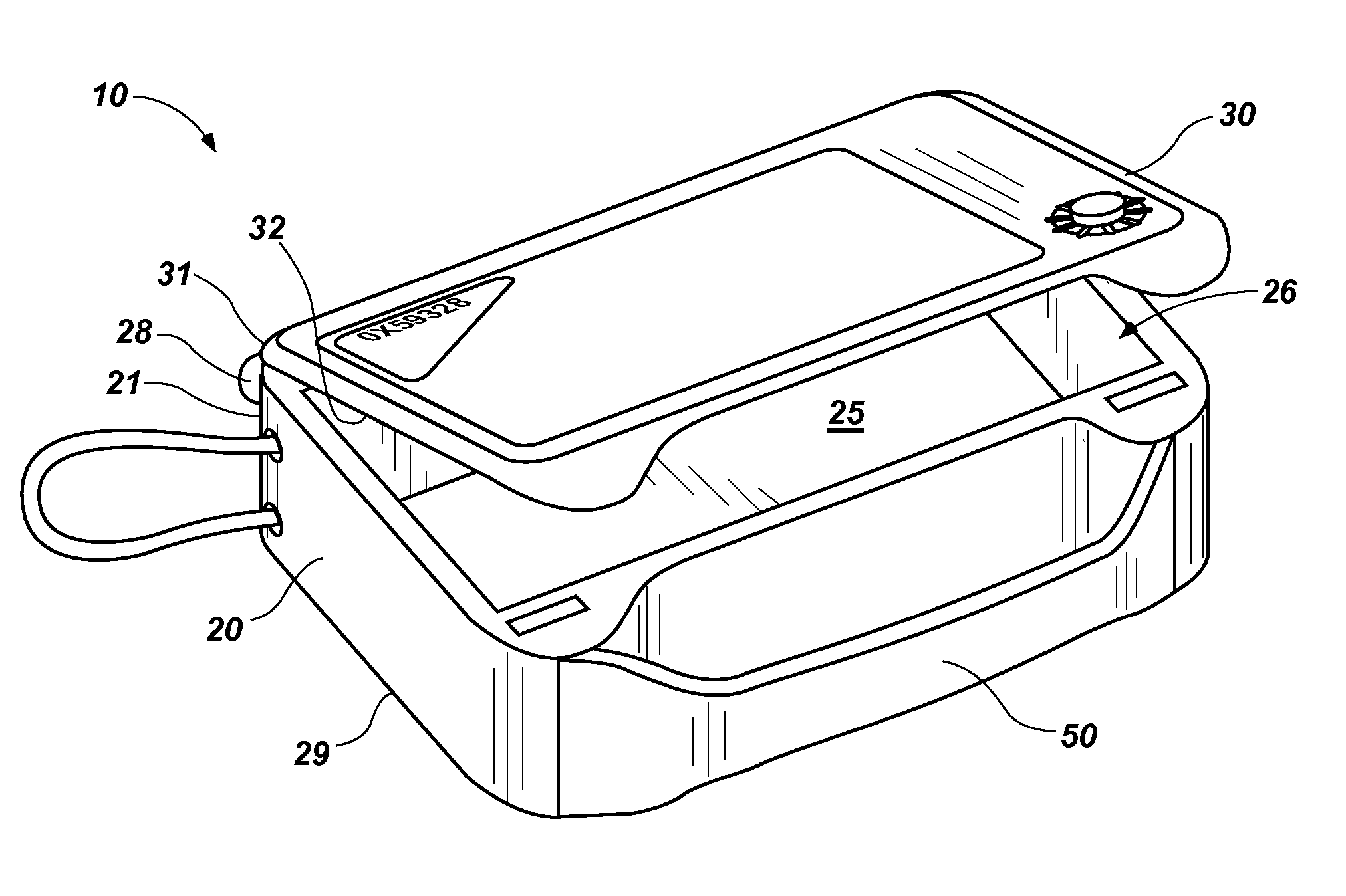
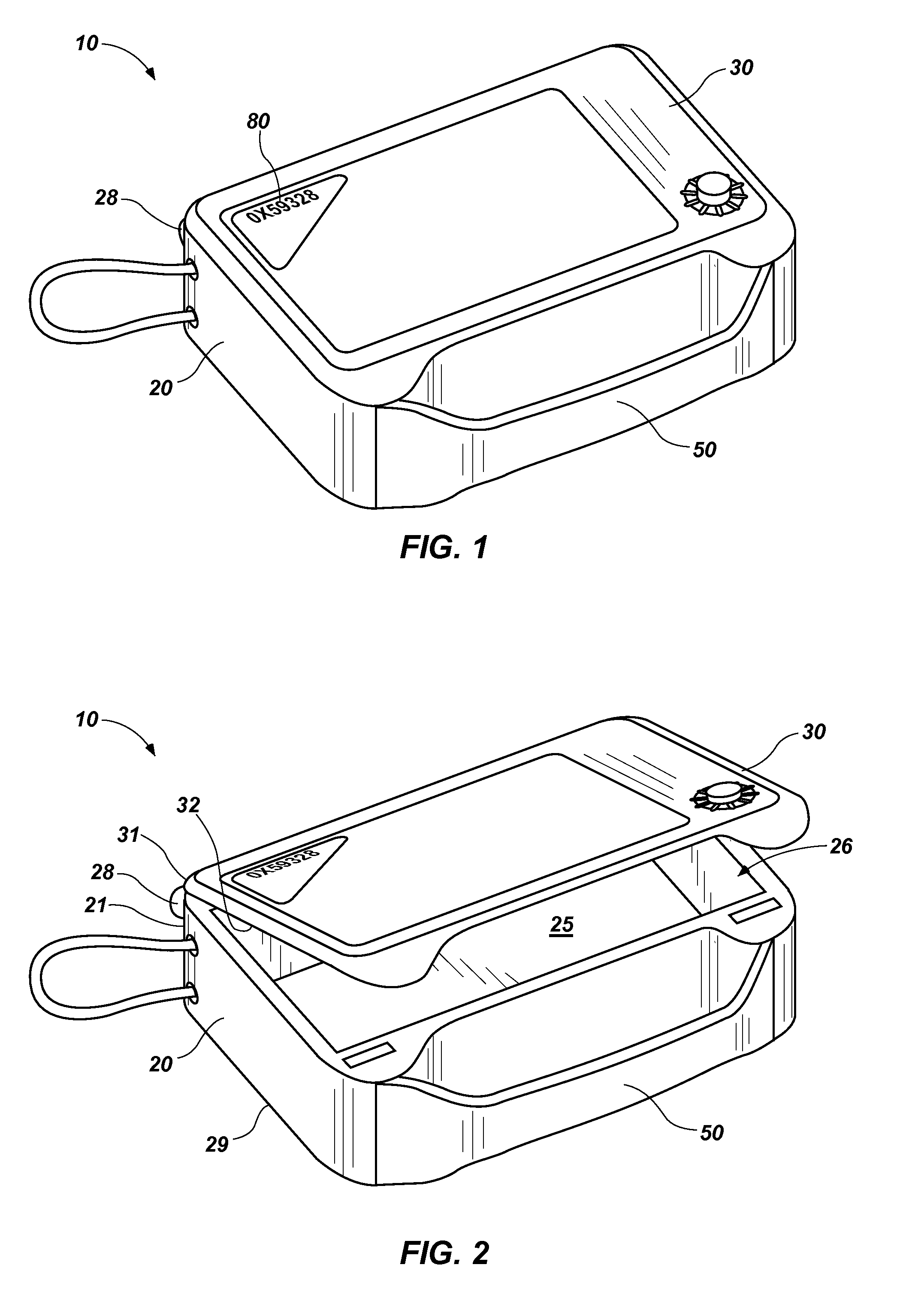
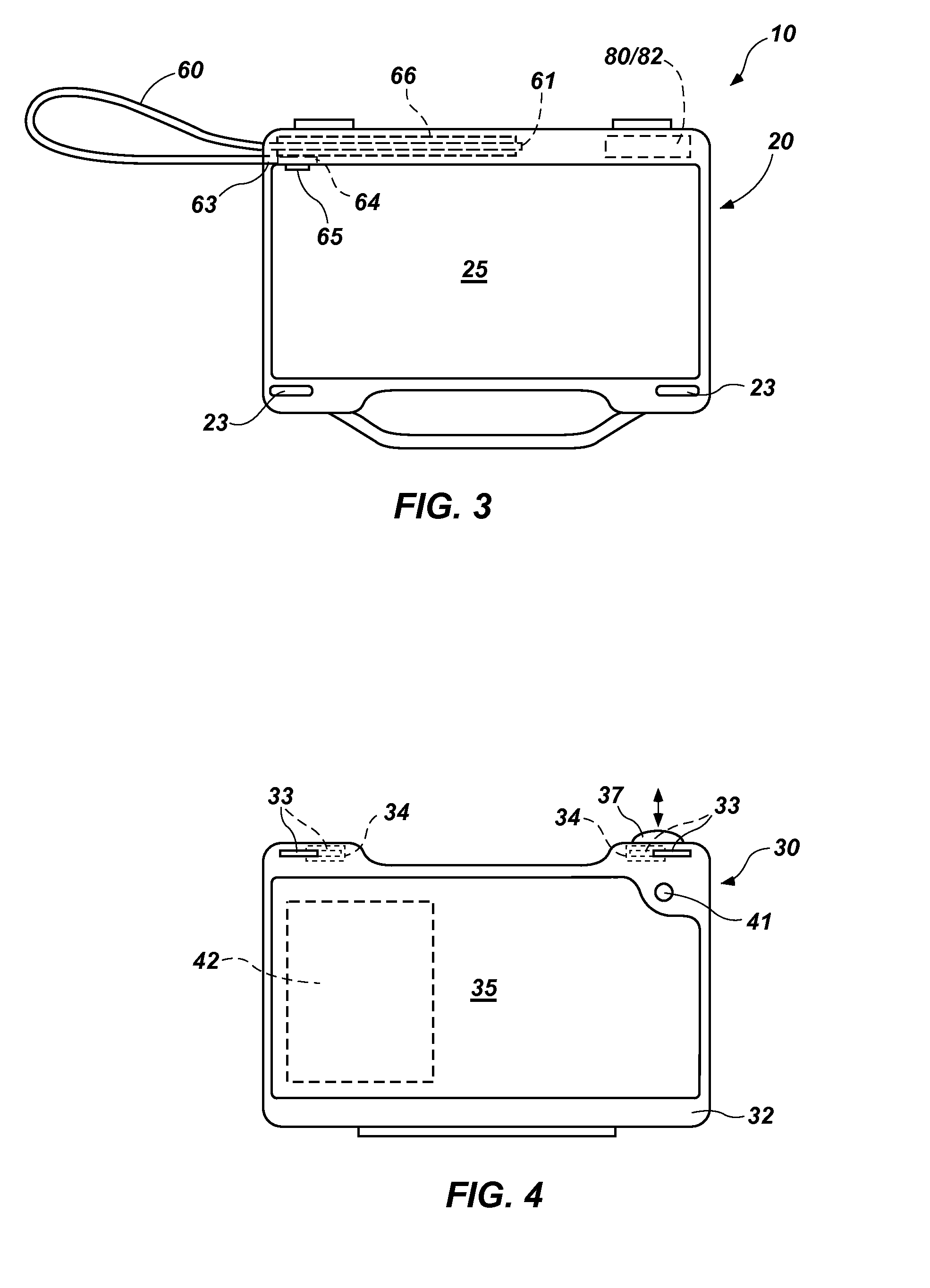
[0028]FIGS. 1 through 8 depict an embodiment of portable safe 10. As illustrated, the portable safe 10 includes container 20, a door 30, a release mechanism 40 and a handle 50, among a variety of other elements.

[0029]As shown in FIGS. 1 and 2, the door 30 of the portable safe 10 is configured to be assembled with the container 20 of the portable safe 10. More specifically, the door 30 may be placed in a closed position over the container 20, as shown in FIG. 1, or the door 30 may be at least partially spaced apart from the container 20 in an at least partially open position, a nonlimiting example of which is shown in FIG. 2. In the illustrated embodiment, one or more hinges 28 at corresponding edges 21 and 31 of the container 20 and the door 30, respectively, may secure the edge 31 of the door 30 to its corresponding edge 21 of the container 20 and guide movement of the door 30 between its closed position and its open position. With the door 30 in the open position, an inner surface...


PUM


Abstract

A portable safe is configured to be temporarily secured to an object without requiring an individual who uses the portable safe to constantly monitor the portable safe or any valuable items secured therein. Thus, the individual may attend to other activities located nearby or remote from the object to which the portable safe is secured. An entity, such as a resort, a hotel or the like may make portable safes available for temporary use by its customers, enabling its customers to portably secure their valuable items. The supplier may rent the portable safes from another entity, which owns the portable safes.

Description

CROSS-REFERENCE TO RELATED APPLICATION[0001]This application claims the benefit of priority under 35 U.S.C. §119(e) to U.S. Provisional Patent Application No. 61 / 488,793, filed May 23, 2011 and titled “Personal Portable Safe, Systems and Methods, pending, the entire disclosure of which is, by this reference, hereby incorporated herein.TECHNICAL FIELD[0002]The subject matter disclosed and claimed by this application relates generally to portable safes or lock boxes and, more specifically, to portable safes and lock boxes that are configured to securely store valuable contents and to be secured retained at a desired location. The disclosed subject matter also relates to systems and methods by which portable safes are provided to individuals for temporary use.RELATED ART[0003]Individuals often travel with valuable items that they may want to periodically access or use during certain activities, but that they may not want to constantly hold onto or keep track of throughout those activit...

Claims


Application Information

Patent Timeline
Patent Type & Authority Applications(United States)
IPC IPC(8): E05G1/04E06B7/16
CPCA45C13/20E05G1/005E05G1/04E05B17/0025E05B65/0075E05B73/0011E05B39/005
Inventor MCCABE, TODD L.
Owner MCCABE TODD L
Learn More