
High-voltage wideband pulse load

a high-voltage wideband and pulse load technology, applied in the direction of high-tension/heavy-dress switch, coupling base/case, electrical apparatus, etc., can solve the problem of difficult to use the prior art high-voltage load b, the external diameter of the hn connector b>13/b> is not large enough to have high-voltage insulation resistance, and the difficulty of storing the resistor sh

Active Publication Date: 2012-11-29
ELECTRONICS & TELECOMM RES INST
View PDF3 Cites 10 Cited by
  • Summary
  • Abstract
  • Description
  • Claims
  • Application Information

AI Technical Summary

Benefits of technology

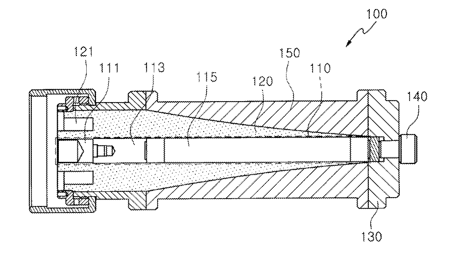
The present invention provides a high-voltage wideband pulse load that can test high-voltage fast transient pulses. The load includes an internal line with a rod resistor and a dielectric substance with a non-linearly decreasing external diameter that matches the resistance of the internal line. The load is housed in a metal external housing. The load has a wideband frequency performance and high-voltage insulation resistance performance simultaneously. The load can be connected to a high-voltage fast transient pulser using a connection connector. The load is designed to minimize pulse dispersion and reflection.

Problems solved by technology

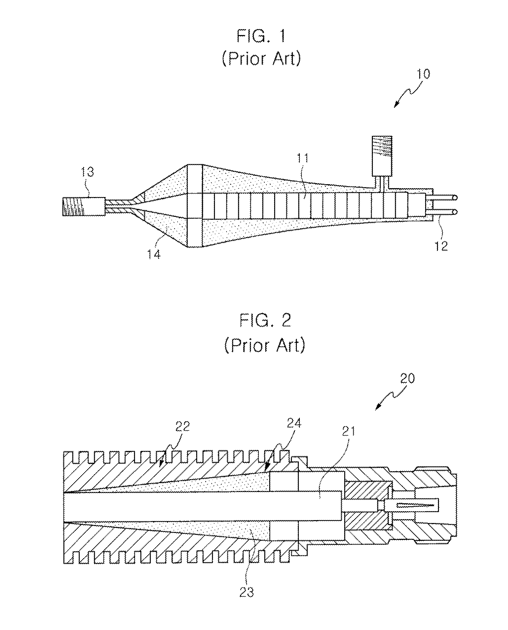
However, since the internal diameter and external diameter of the high-voltage load 10 are designed to correspond to specific impedance, the external diameter of the HN connector 13 is not large enough to have high-voltage insulation resistance because of the restricted internal diameter.
As described above, there is a problem because it is difficult to use the prior art high-voltage load 10 as a high-voltage pulse load.
The key idea of the coaxial cable load 20 in the aspect of structural characteristic is that of deposited sheet resistance on the surface between dielectrics and external housing, but has the problem in that it is difficult to deposit the sheet resistor regularly having wanted specific impedance, thereby being difficult to implement target impedance accurately.
However, since the characteristics of the two performances conflict with each other, it is difficult to solve the problem using the prior art technology.

Method used


Image

  • High-voltage wideband pulse load
  • High-voltage wideband pulse load
  • High-voltage wideband pulse load

Examples


Embodiment Construction

[0036]The present invention will be described in detail with reference to the accompanying drawings below. Here, in cases where the description would be repetitive and detailed descriptions of well-known functions or configurations would unnecessarily obscure the gist of the present invention, the detailed descriptions will be omitted. The embodiments of the present invention are provided to complete the explanation of the present invention to those skilled in the art. Therefore, the shapes and sizes of components in the drawings may be exaggerated to provide a more exact description.

[0037]A high-voltage wideband pulse load according to embodiments of the present invention will be described with reference to the accompanying drawings below.

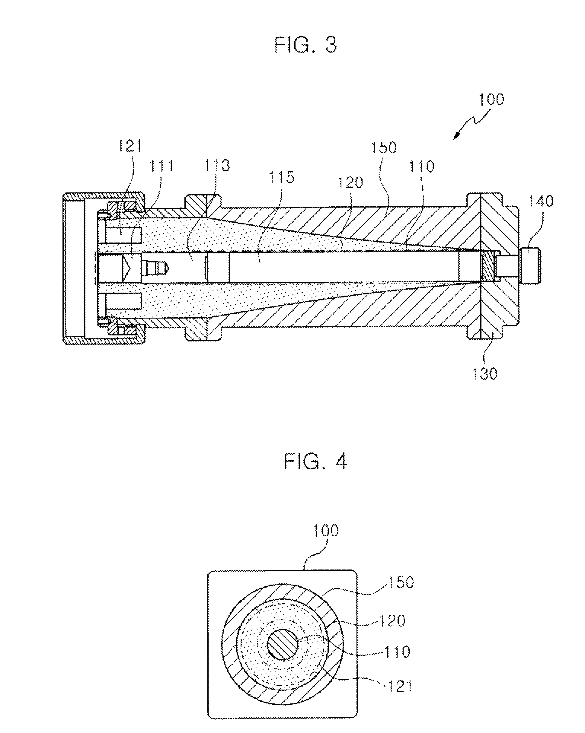
[0038]First, a high-voltage wideband pulse load according to an embodiment of the present invention will be described with reference to FIGS. 3 and 4.

[0039]FIG. 3 is a longitudinal section view illustrating a high-voltage wideband pulse load accor...


PUM


Abstract

A high-voltage wideband pulse load is provided. The high-voltage wideband pulse load includes an internal line, a dielectric substance, and an external housing. The internal line includes input terminal, connection electrode and a rod resistor. The resistance of the internal line linearly increases along the moving direction of an incoming pulse by the rod resistor. The dielectric substance is coupled to the internal line in a coaxial structure which covers the exterior of the internal line, and is configured to have a shape of a non-linearly decreasing external diameter along the moving direction so that impedance linearly decreases along the moving direction in contrast with the resistance of the internal line. The external housing is coupled to the dielectric substance in a coaxial structure which covers the exterior of the dielectric substance, and is formed of metal.

Description

CROSS REFERENCE TO RELATED APPLICATION[0001]This application claims the benefit of Korean Patent Application No. 10-2011-0048715, filed on May 23, 2011, which is hereby incorporated by reference in its entirety into this application.BACKGROUND OF THE INVENTION[0002]1. Technical Field[0003]The present invention relates generally to a high-voltage wideband pulse load, and, more particularly, to a high-voltage wideband pulse termination load which has the wideband frequency performance of a high-voltage pulse.[0004]2. Description of the Related Art[0005]FIG. 1 is a view illustrating a prior art high-voltage load.[0006]As shown in FIG. 1, a high-voltage load 10 includes a plurality of ceramic resistive elements 11 which are arranged in a stacked structure on a coaxial line, and includes a cable termination device 12 which terminates input impedance to 50 ohm.[0007]The high-voltage load 10 includes an HN connector 13 which functions as an input terminal, and includes a dielectric substan...

Claims


Application Information

Patent Timeline
Patent Type & Authority Applications(United States)
IPC IPC(8): H01P1/26
CPCH01P1/26H01P1/264H01R13/53H01B17/26H01H33/04
Inventor RYU, SEUNG-KABLEE, KYUNG-HOON
Owner ELECTRONICS & TELECOMM RES INST
Learn More