Installation structure of thin-type display and resistive film type touch panel, resistive film type touch panel unit with front-surface protrusions, and thin-type display unit with back-surface protrusions

a technology of resistive film type and touch panel, which is applied in the direction of instruments, computing, electric digital data processing, etc., can solve the problems of inability to carry out input with a pen, impaired excellent visibility inherent in electronic paper b>101/b>, and large eye burden, so as to achieve easy and sure input and easy to carry out

Active Publication Date: 2012-11-29
NISSHA PRINTING COMPANY
View PDF7 Cites 69 Cited by
  • Summary
  • Abstract
  • Description
  • Claims
  • Application Information

AI Technical Summary

Benefits of technology

[0022]According to the present invention, the installation structure of a thin-type display and a resistive film type touch panel includes: a resistive film type touch panel that is disposed on the back surface side of a thin-type display; and a multitude of protrusions disposed between the thin-type display and the resistive film type touch panel, and are fixed to one of the thin-type display and the resistive film type touch panel. Accordingly, even in a case where a normal load is applied to the front surface of the thin-type display and deformation occurs evenly on the entire thin-type display due to the rigidity of the thin-type display, the protrusions locally push in the movable electrode film of the resistive film type touch panel. That is, an input is carried out just like the manner in which an input is carried out with a finger or a stylus pen directly to the movable electrode film of the resistive film type touch panel. Accordingly, an input can easily be carried out. As a result, a point-like input can easily and surely be carried out.
[0023]Further, the resistive film type touch panel unit with front-surface protrusions or the thin-type display unit with back-surface protrusions of the present invention can be used for the installation structure of a thin-type display and a resistive film type touch panel described above, and can exhibit the operation and effect described above.

Problems solved by technology

This invites a problem that the excellent visibility that is inherent to the electronic paper 101 is impaired, and burden on the eyes is great.
However, with the capacitive type touch panel, an input cannot be carried out with a pen.

Method used


Image

  • Installation structure of thin-type display and resistive film type touch panel, resistive film type touch panel unit with front-surface protrusions, and thin-type display unit with back-surface protrusions
  • Installation structure of thin-type display and resistive film type touch panel, resistive film type touch panel unit with front-surface protrusions, and thin-type display unit with back-surface protrusions
  • Installation structure of thin-type display and resistive film type touch panel, resistive film type touch panel unit with front-surface protrusions, and thin-type display unit with back-surface protrusions

Examples


Embodiment Construction

[0042]Before the description of the present invention proceeds, it is to be noted that like parts are designated by like reference numerals throughout the accompanying drawings.

[0043]In the following, before describing embodiments of the present invention in detail with reference to the drawings, a description will be given of various aspects of the present invention.

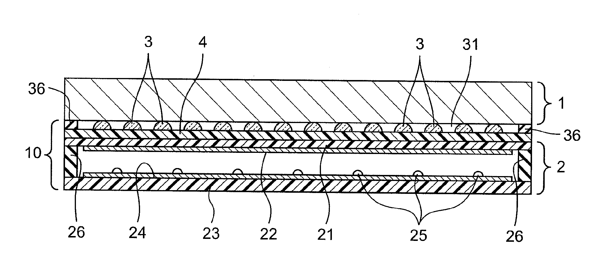
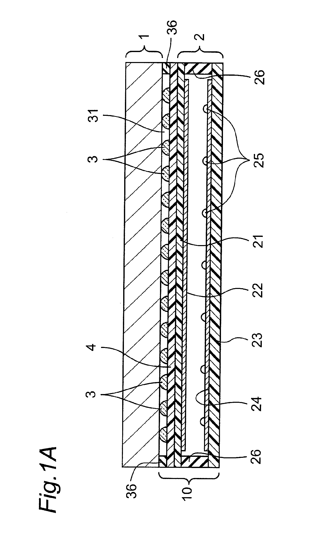
[0044]According to a first aspect of the present invention, there is provided an installation structure of a thin-type display and a resistive film type touch panel, comprising:

[0045]a paper-like thin-type display;

[0046]a resistive film type touch panel that is disposed on a back surface side of the thin-type display; and

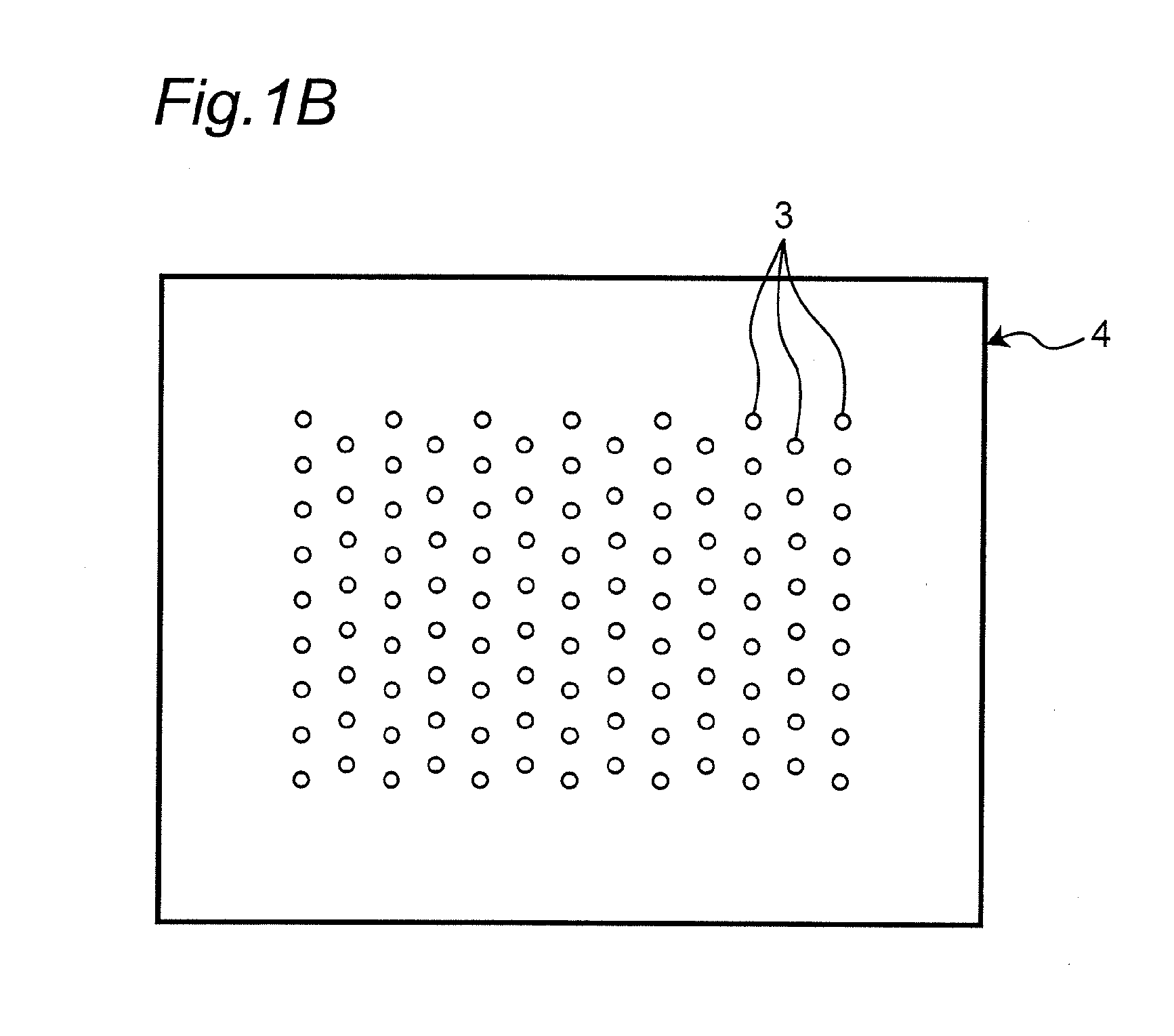
[0047]a multitude of protrusions that are disposed between the thin-type display and the resistive film type touch panel and that are fixed to one of the thin-type display and the resistive film type touch panel.

[0048]According to a second aspect of the present invention, there is provided the installat...


PUM

PropertyMeasurementUnit
heightaaaaaaaaaa
heightaaaaaaaaaa
diameteraaaaaaaaaa

Abstract

An installation structure of electronic paper and a resistive film type touch panel, includes electronic paper, a resistive film type touch panel disposed on a back surface side of the electronic paper, and a multitude of protrusions that are disposed between the electronic paper and the resistive film type touch panel, and that are fixed to at least one of the electronic paper and the resistive film type touch panel.

Description

TECHNICAL FIELD[0001]The present invention relates to an installation structure of a thin-type display and a resistive film type touch panel, and a resistive film type touch panel unit with front-surface protrusions and a thin-type display unit with back-surface protrusions both of which are used for the installation structure of a thin-type display and a resistive film type touch panel, all of which exhibit excellent visibility of the thin-type display, and with which an input with a pen or a finger is carried out easily.BACKGROUND ART[0002]Conventionally, there is a display media referred to as electronic paper. The electronic paper maintains visibility and portability which are regarded as the advantage of paper, and allows the displayed content to be electrically rewritten. The representative display technique of the electronic paper is the electrophoretic system. Electronic paper 101 of this system is developed by E Ink Corporation, US. In the electronic paper 101 of this schem...

Claims


Application Information

Patent Timeline
Patent Type & Authority Applications(United States)
IPC IPC(8): G06F3/045G02F1/167G02F1/1675
CPCG02F1/13338G06F3/045G02F1/167G02F1/1675
Inventor NISHIKAWA, KAZUHIROSUNAHASE, TAKAKUNI
Owner NISSHA PRINTING COMPANY
Why Eureka
Try Eureka