Air distribution for an air seeder

a technology of air seeder and air distribution, which is applied in the direction of seeding, seeding seeder parts, application, etc., can solve the problems of reducing yield and/or quality of crop on the twice seeded field area, and most undesirable to leave even a narrow strip of a field unneeded, etc., to achieve constant air flow, reduce the volume of air moved, and speed up the air stream

Active Publication Date: 2012-11-29
BOURGAULT INDS
View PDF7 Cites 43 Cited by
  • Summary
  • Abstract
  • Description
  • Claims
  • Application Information

AI Technical Summary

Benefits of technology

The patent describes a type of blower that can be used for air seeders. These blowers provide a constant volume of air as the pressure downstream increases. This helps to maintain the critical velocity of the air stream in the supply conduit. However, if there are fewer open ports in the manifold, more air must flow through each open port, which can increase the speed of the air stream in the delivery conduits. Overall, these blowers help to ensure a consistent and efficient air seeding process.

Problems solved by technology

The technical problem addressed in this patent is how to stop the delivery of agricultural products to furrow openers in the overlap area when a strip of a field to be seeded is narrower than the seeder, without wasting valuable seed and fertilizer and compromising the yield and quality of the crop.

Method used


Image

  • Air distribution for an air seeder
  • Air distribution for an air seeder
  • Air distribution for an air seeder

Examples


Embodiment Construction

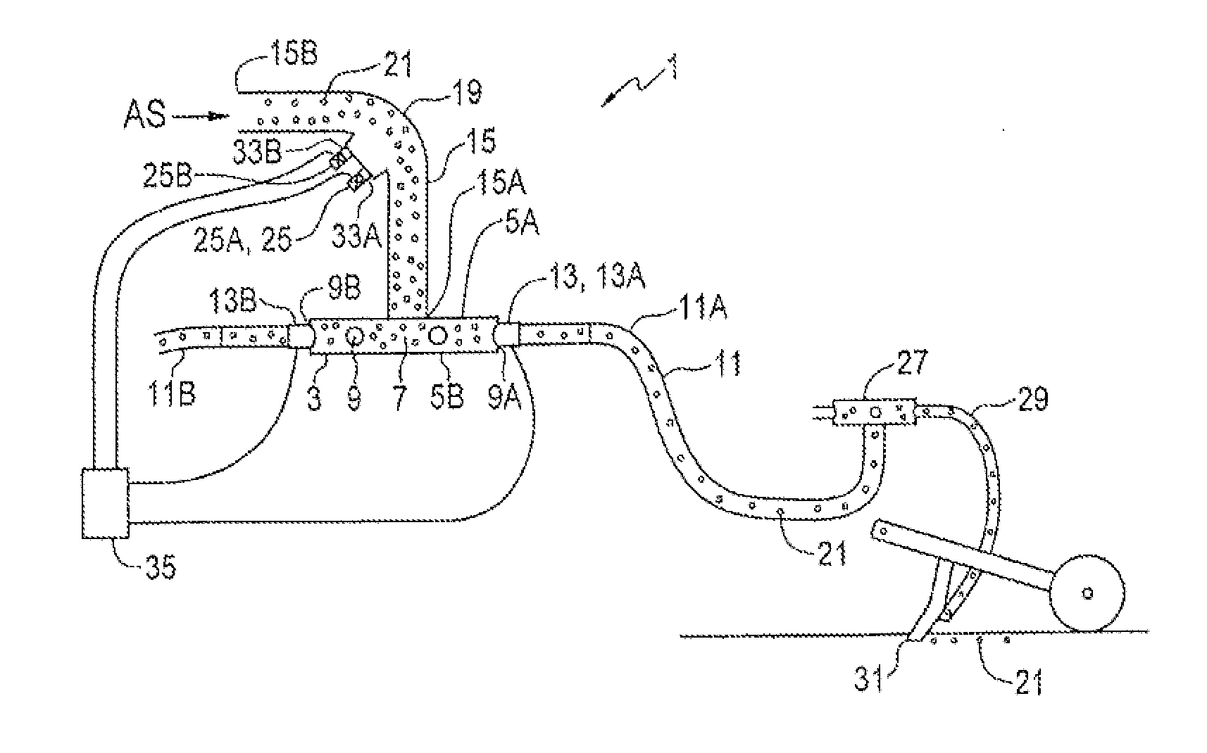
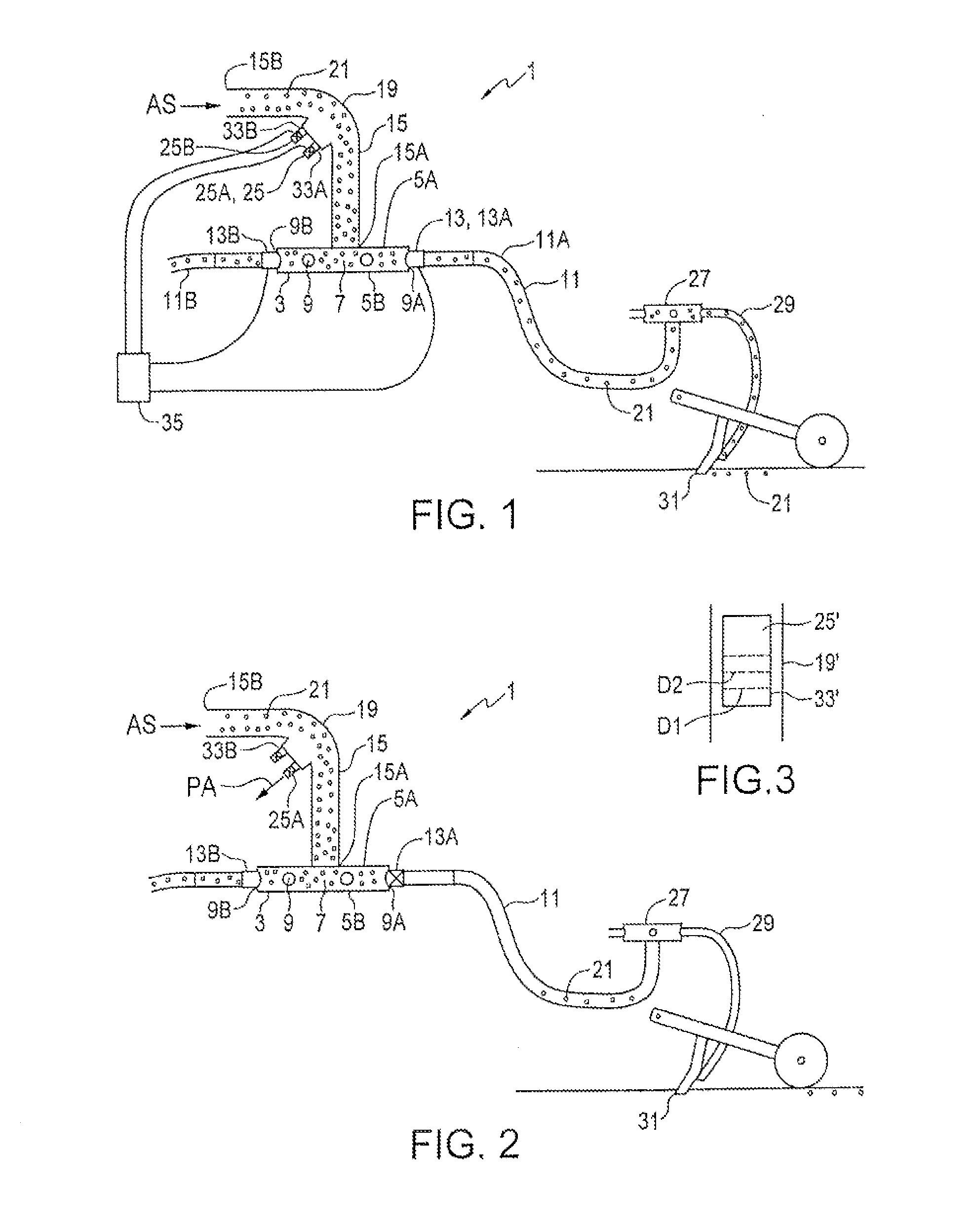
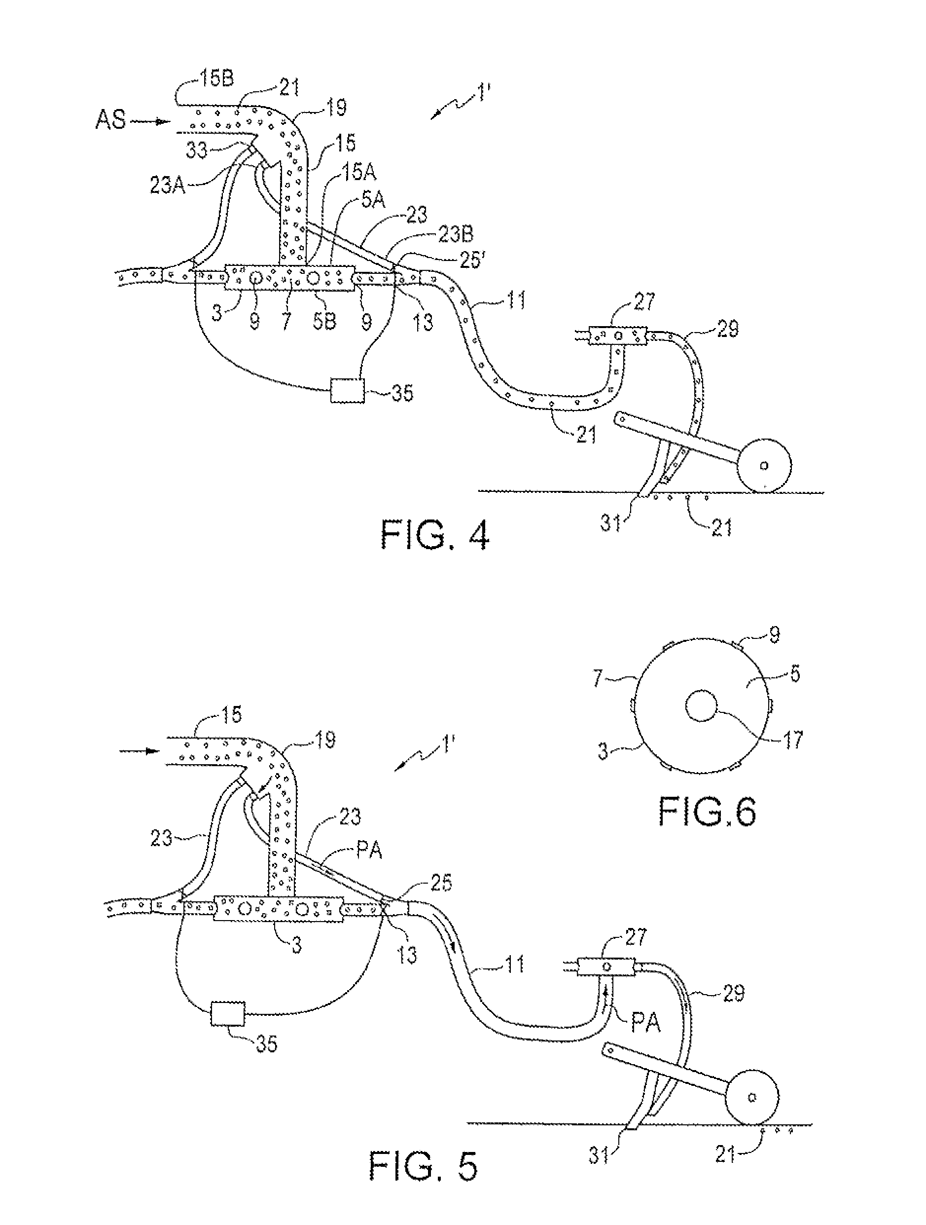
[0038]FIGS. 1 and 2 schematically illustrate an embodiment of an air distribution apparatus 1 of the present invention. The apparatus 1 is shown as part of an air seeder product distribution network. The apparatus 1 comprises a manifold body 3 comprising substantially circular top and bottom plates 5, as illustrated in FIG. 6, oriented substantially horizontally, and a substantially vertical body wall 7 extending between the top and bottom plates 5A, 5B. Ports 9 are defined through the body wall 7, and a delivery conduit 11 is connected to each port 9.

[0039]A port valve 13 is configured such that when the port valve 13 is open, as illustrated in FIG. 1, the delivery conduit 11 is connected to the interior of the manifold body 3 through the port 9, and such that when the port valve 13 is closed, as illustrated in FIG. 2, the delivery conduit 11 is disconnected from the interior of the manifold body 3.

[0040]A substantially vertically oriented supply conduit 15 is connected at an outpu...


PUM


Abstract

An air distribution apparatus has a manifold body, and ports defined through walls thereof, with a delivery conduit connected to each port. A port valve is configured to connect and disconnect the delivery conduit to the interior of the manifold body. A supply conduit delivers a product air stream with agricultural products entrained therein to the interior of the manifold body. The supply conduit extends vertically up from the manifold to a curved elbow and then extends horizontally from the elbow. An exhaust orifice is defined in the inner radius of the elbow. When an exhaust valve is open, a selected flow of pressurized air flows from the supply conduit through the exhaust orifice. The port valve and exhaust valve are controlled such that when the port valve closes, the exhaust valve opens. The exhaust air can be directed into the delivery conduits to clear product therefrom.

Description


Claims


Application Information

Patent Timeline
Owner BOURGAULT INDS
Why Eureka
Try Eureka