Compressor

a compression device and compression chamber technology, applied in the field of compression devices, can solve the problems of difficult to reduce pulsation, difficult to maintain a high compression efficiency, and prone to sealing defects, and achieve the effect of increasing manufacturing costs

Inactive Publication Date: 2012-11-29
TOYOTA IND CORP
View PDF15 Cites 45 Cited by
  • Summary
  • Abstract
  • Description
  • Claims
  • Application Information

AI Technical Summary

Benefits of technology

[0030]Any one of a knurling process, a blasting process, and a laser process ensures that a gap having small variations is obtained between the reed valve and the seating surface. Fur...

Problems solved by technology

However, in the compressors of documents 1 to 3, it is difficult to reduce pulsation while maintaining high compression efficiency and lowering costs.
Thus, sealing defects are apt to occur.
In such a case, ...

Method used


Image

  • Compressor
  • Compressor
  • Compressor

Examples


first embodiment

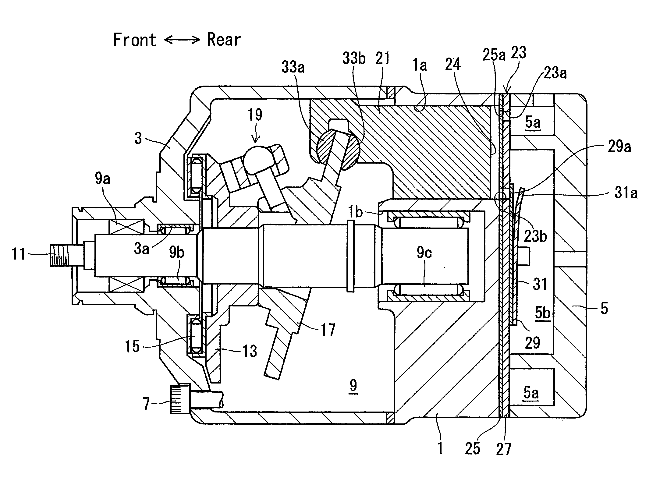
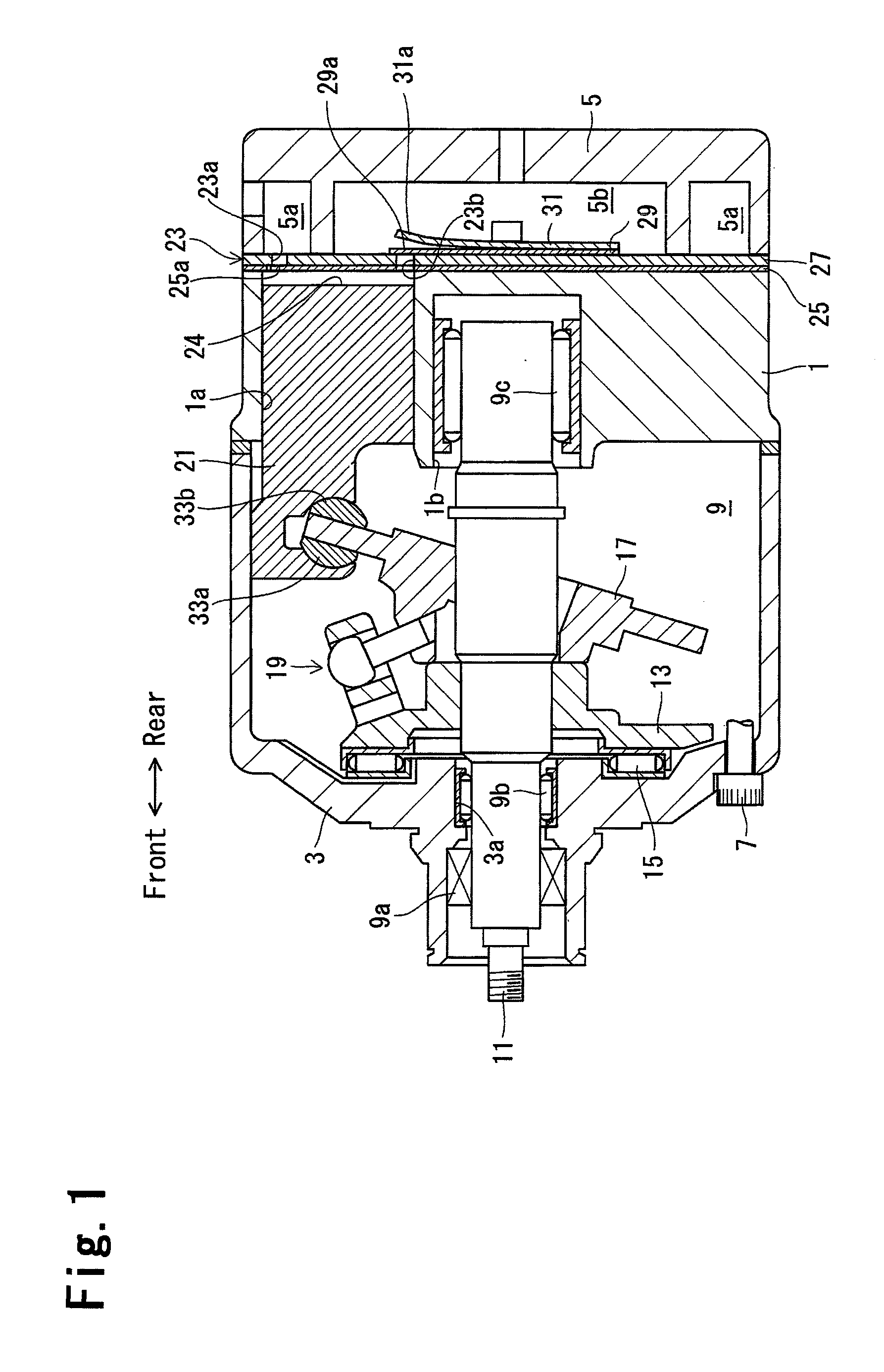
[0052]Referring to FIG. 1, a housing of the compressor in the first embodiment includes a cylinder block 1, a front housing member 3, which is joined with the front end of the cylinder block 1, and a rear housing member 5, which is joined with the rear end of the cylinder block 1 with a valve unit 23 arranged in between. A plurality of bolts 7 fasten the cylinder block 1, the front housing member 3, and the rear housing member 5 to one another. The cylinder block 1 includes a plurality of cylinder bores 1a. The cylinder bores 1a are arranged at equal angular intervals along the same circle and extend parallel to one another along the axis of the cylinder block 1. The cylinder block 1 and the front housing member 3 form a crank chamber 9. The rear housing member 5 includes a suction chamber 5a, which is located at an outer part in the radial direction, and a discharge chamber 5b, which is located at a central part in the radial direction.

[0053]The front housing member 3 includes a sh...

second embodiment

[0075]FIGS. 7 and 8 illustrate main parts of a compressor according to a second embodiment of the present invention.

[0076]As shown in FIGS. 7 and 8, the discharge ports 23b are formed in the suction valve plate 25 and the valve plate 27 to communicate the discharge chamber 5b and the compression chambers 24. The discharge valve plate 29 includes the discharge reed valves 29a, which open and close the discharge ports 23b. In the present embodiment, referring to FIG. 8, the discharge valve plate 29 is formed from an elastically deformable thin plate, and the discharge reed valves 29a extend radially.

[0077]Referring to FIGS. 8 to 10, the discharge port 23b is circular when viewed from above. The surface of the valve plate 27 facing the discharge chamber 5b, that is, the surface facing the discharge valve plate 29, defines a seating surface 275. The seating surface 275 includes annular grooves 277 entirely surrounding the discharge ports 23b, that is, entirely surrounding opening edges....

third embodiment

[0088]Referring to FIGS. 16 and 17, in a compressor of a third embodiment, a formation range of the plurality of protrusions 273a is changed from the first embodiment. More specifically, a plurality of protrusions 273b in the third embodiment are formed continuously in a region extending from the vicinity of the discharge port 23b to a rim 272a of the groove 272 on the reference surface 273 in the first direction D1. The protrusions 273b are continuous with the rim 272a of the groove 272.

[0089]The surface of the valve plate 27 facing the discharge chamber 5b, that is, the surface facing the discharge valve plate 29, defines the seating surface 275. The seating surface 275 includes annular grooves 277 entirely surrounding the discharge ports 23b, that is, entirely surrounding opening edges. As shown in FIG. 17, the protrusions 273b are separated from the region of the reference surface 273 located at the opposite side of the grooves 277. In the same manner as the protrusions 272a of ...


PUM


Abstract

A compressor includes a valve plate, a suction reed valve, and a seat surface. The valve plate has a suction port that communicates with a compression chamber and a suction chamber. The suction reed valve can open and close the suction port. The seat surface is formed on the valve plate, and is abutted with the suction reed valve when the suction reed valve closes the suction port. The seat surface includes a flat seal surface surrounding the suction port, and a groove surrounding the seal surface. The valve portion of the suction reed valve includes a flat sealing surface which is brought into close contact with the seal surface to close the suction port. The seat surface has a plurality of protrusions which space the seal surface from the sealing surface when the pressures of the compression chamber and the suction chamber are identical.

Description

FIELD OF THE INVENTION[0001]The present invention relates to a compressor.BACKGROUND OF THE INVENTION[0002]A typical compressor includes a partition wall arranged between a compression chamber and a suction chamber. A suction port extends through the partition wall thereby allowing for communication of the compression chamber and the suction chamber. A suction reed valve opens and closes the suction port. The partition wall includes a seating surface. The suction reed valve comes into contact with the seating surface when closing the suction port. The suction reed valve includes a fixed portion, which is fixed to the partition wall, a base portion, which extends from the fixed portion along the partition wall and is movable toward and away from the partition wall, and a valve portion, which extends from the base portion along the partition wall to open and close the suction port.[0003]When the pressure of the compression chamber increases and becomes higher than the pressure of the ...

Claims


Application Information

Patent Timeline
IPC IPC(8): F04B39/10F16K15/16F04B53/10
CPCF04B27/1009F04B39/1066F04B39/1073F16K27/0209F04B53/105F16K15/16F04B53/1047Y10T137/7891F05B2210/14F05B2210/12
Inventor OTA, MASAKIMURASE, MASAKAZUKUBO, HIROSHISATAKE, NORIAKIKAWAGUCHI, MASAHIRO
Owner TOYOTA IND CORP
Why Eureka
Try Eureka