
Single belt omni directional treadmill

a treadmill and single belt technology, applied in the field of treadmills, can solve the problems of deprived users of the inertia they would normally feel, inconsistent or slightly disconnected sensation,

Active Publication Date: 2012-11-29
INFINADECK CORP
View PDF15 Cites 32 Cited by
  • Summary
  • Abstract
  • Description
  • Claims
  • Application Information

AI Technical Summary

Benefits of technology

[0007]Unlike the prior art as exemplified by U.S. Pat. No. 7,780,573 which requires multiple belts, the present invention is an omni-directional treadmill that employs only one conveyor belt and is much simpler in nature and simpler to build. Instead of having a separate conveyer belt for each treadmill segment, the omni-directional treadmill of the present invention employs a single conveyer belt. Instead of having a separate conveyor belt for each treadmill segment, the omni-directional treadmill of the present invention employs a single conveyor belt. The present invention thereby provides the advantages of not needing an elaborate method to connect end rollers to transfer movement of one belt to the next, thus eliminating the need to individually adjust tensions on a multitude of belts. This single belt is fed from one high aspect ratio cross beam to the next. All cross beams are attached to two common roller chains positioned underneath and near the end of each beam. These common roller chains then move a flat track with sprockets at each end.
[0009]Control for the motors that power the omni-directional treadmill may be accomplished in several ways. One means would be to incorporate an infrared sensing device like an Xbox Kinect to keep track of the user's direction, speed and acceleration on the treadmill and using that information to keep the user balanced and mostly centered.
[0012]According to another aspect of the present invention, the omni-directional treadmill is designed such that it can tilt in both the X and Y directions. Tilting control can be tied to the speed controller, enabling the omni-directional treadmill to be programmed to tilt in proportion to a user's small acceleration. The omni-directional treadmill can be programed to tilt up in the direction of that acceleration if the user was increasing speed and down if reducing speed, tilting as high or low and lasting as long as the controlling acceleration dictates. This tilting forces the user to work a little harder just as if she actually were accelerating her own weight in the direction she was running or turning, giving her the anticipated feeling associated with acceleration.
[0013]Another or additional way of controlling the treadmill of the present invention is to use a dynamic control interface. The illustrative control interface described here attaches the user to the machine via a swivel harness. The attachment allows the user to bend forward, sideways, jump up and pivot in any direction. It also allows her limited movement. This movement provides the controller with the user's position and acceleration. It also allows for a way of dampening her movement to simulate inertia. An additional feature of this system is that it provides a means to modify the user's apparent weight. She can weigh as much or as little as she desires via the harness interface. And still another feature is that it makes sure that the user cannot accidently run off the platform.

Problems solved by technology

While this is most likely sufficient for movement, it deprives the user of the inertia the user would normally feel if actually moving.
This most likely would give the user an inconsistent or slightly disconnected sensation.

Method used


Image

  • Single belt omni directional treadmill
  • Single belt omni directional treadmill
  • Single belt omni directional treadmill

Examples


Embodiment Construction

[0040]Persons of ordinary skill in the art will realize that the following description of the present invention is illustrative only and not in any way limiting. Other embodiments of the invention will readily suggest themselves to such skilled persons.

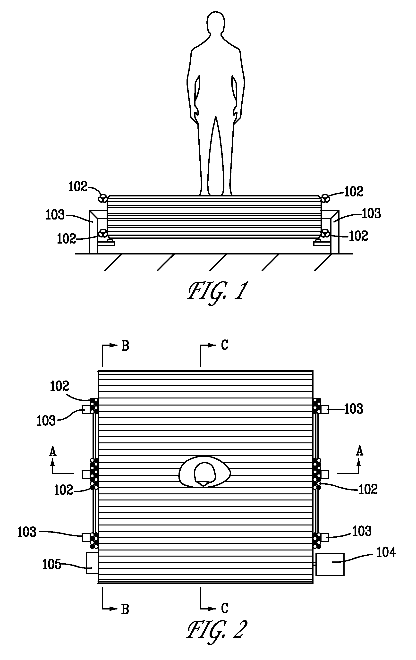
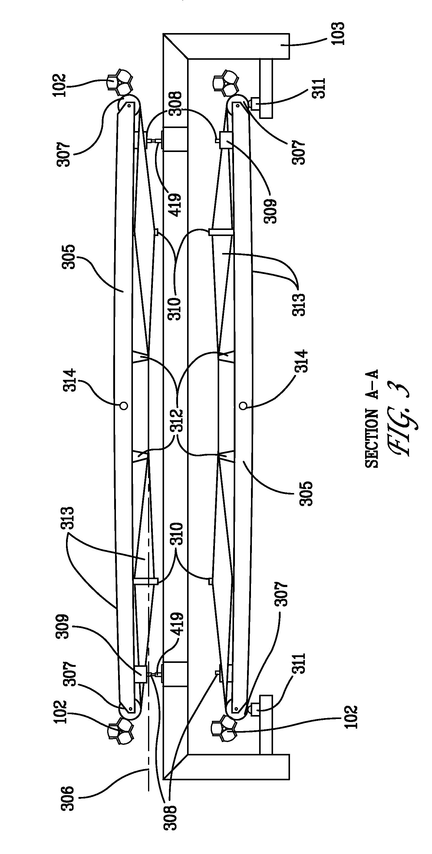
[0041]Construction and operation of an illustrative treadmill of the present invention is shown in the various views presented in FIGS. 1 through 7. The treadmill functions by mounting a series of cross beams 305 on two roller chains 308, one roller chain near each end of the beam as shown in FIG. 7. Cross beams 305 may be formed from a material such as aluminum. The roller chains 308 are assembled to form two parallel chains, each with a sprocket 204 on each end, the sprocket bearings being fixed to a frame 103. Movement of these beams on the chain assembly allow for movement in the x direction. For movement on the y direction, a single helically wound conveyer belt 313 is employed. Conveyor belt 313 may be formed from polyester mono...


PUM


Abstract

A treadmill having a belt assembly allows a user the walk or run in any direction. A single helically wound belt over a flattened torus is powered by two independent drive systems. The drive systems are controlled by a combination of infrared cameras and a physical harness system.

Description

RELATED APPLICATIONS[0001]The present application claims priority to U.S. Provisional Application Ser. No. 61 / 400,535, filed on Jul. 29, 2010, the entirety of which is incorporated by reference herein.BACKGROUND[0002]1. Field of the Invention[0003]The present invention relates to a treadmill that can be walked on in any direction without physically moving from one small area. The treadmill of the present invention will be able to greatly enhance the immerging technology of immersive virtual reality along with many other technologies.[0004]2. Description of Related Art[0005]Several types of omni-directional treadmills or similar functioning devices are known. One such treadmill is disclosed in U.S. Pat. No. 7,780,573 and employs a plurality of high aspect ratio endless unpowered treadmills fixed together transverse to the plane of belt rotation enabling them to move together like the treads of a tank. The plurality of treadmills is then powered by having them pass over several omni-d...

Claims


Application Information

Patent Timeline
IPC IPC(8): A63B22/02
CPCA63B21/0087A63B22/0023A63B22/0242A63B22/0257A63B2022/0271A63B69/0064A63B22/00A63B22/02A63B22/0285A63B23/00
Inventor BURGER, GEORGE
Owner INFINADECK CORP
Learn More